


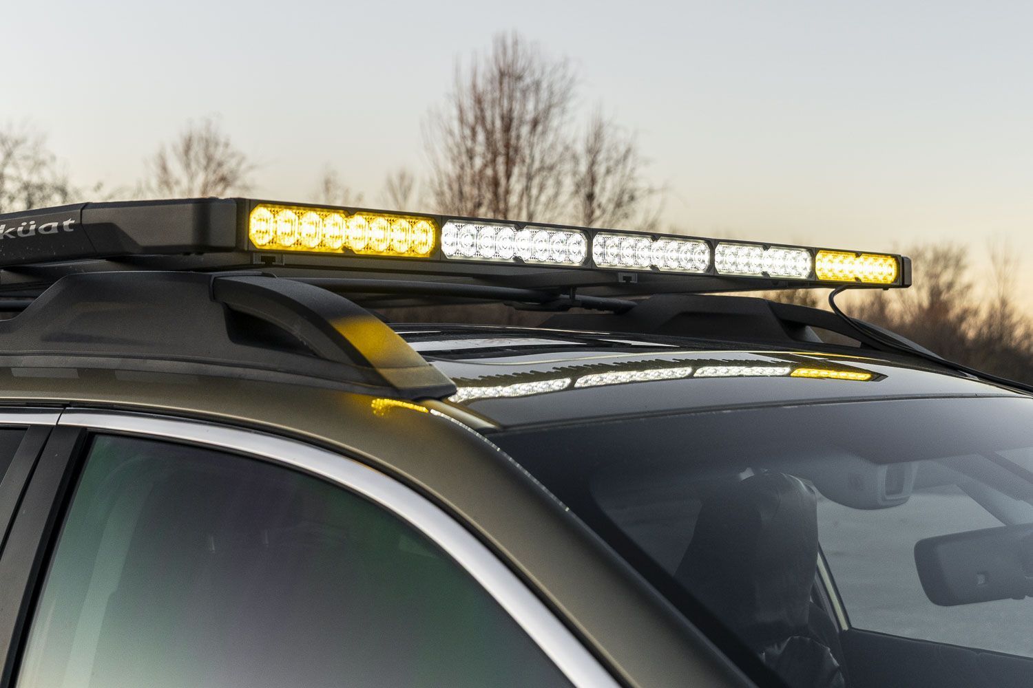
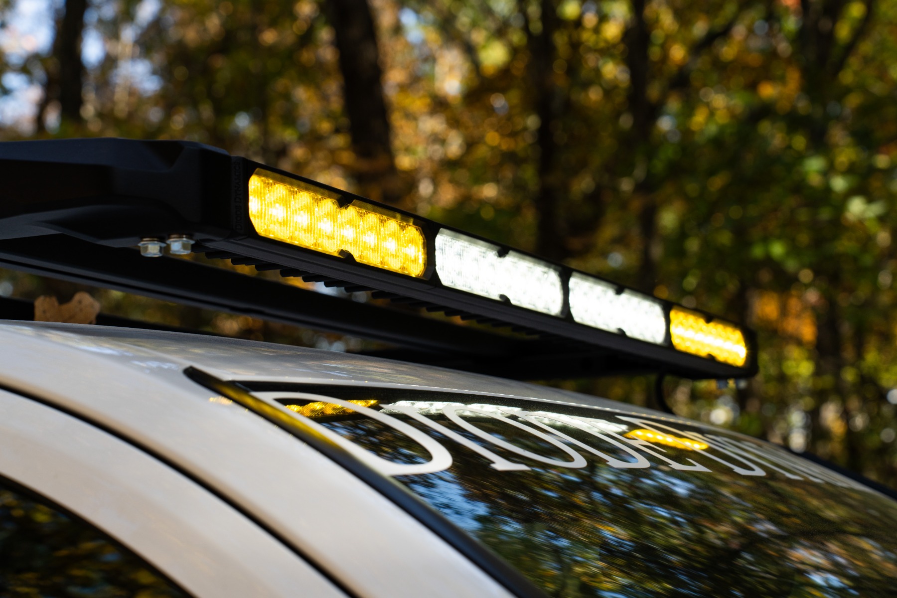
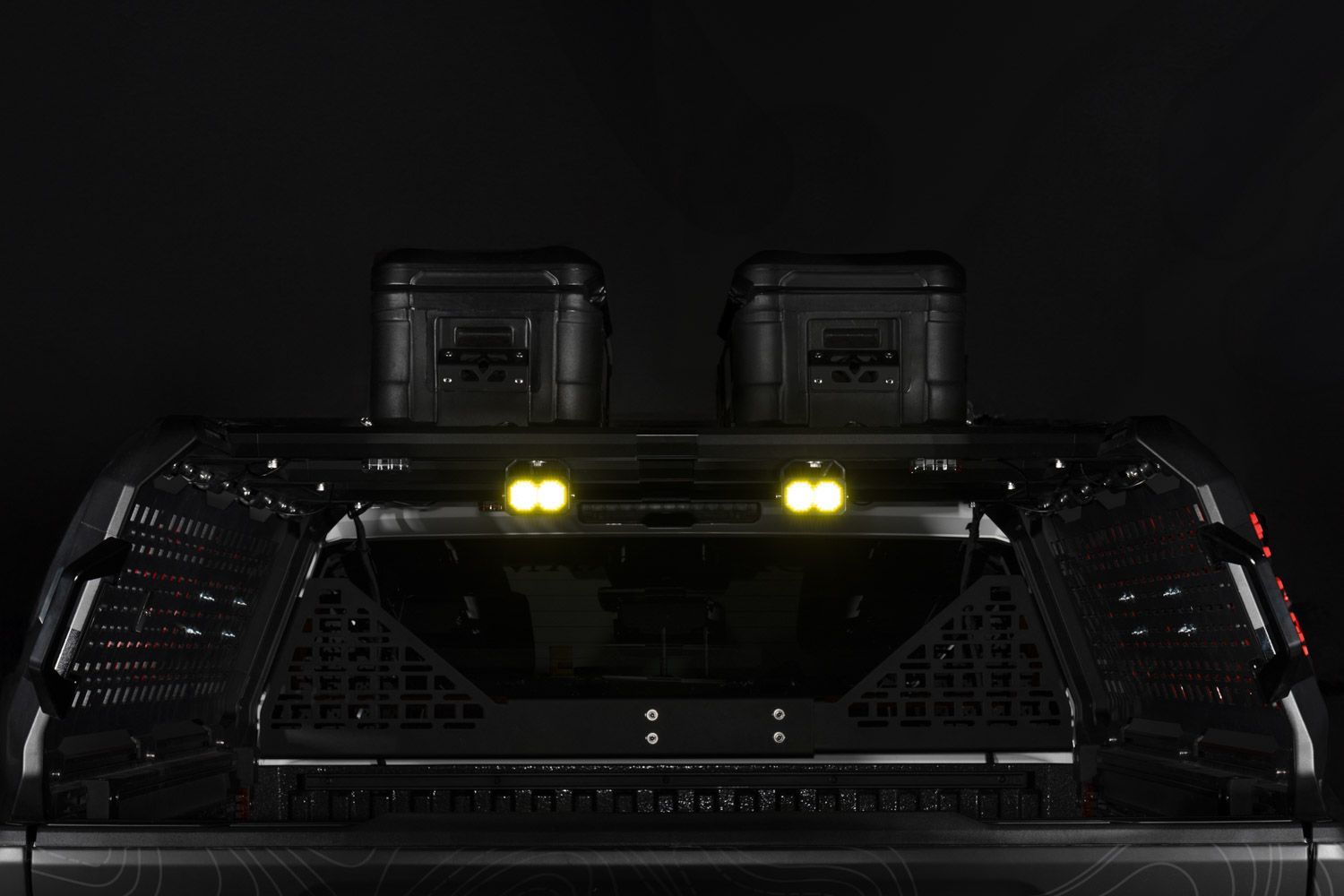
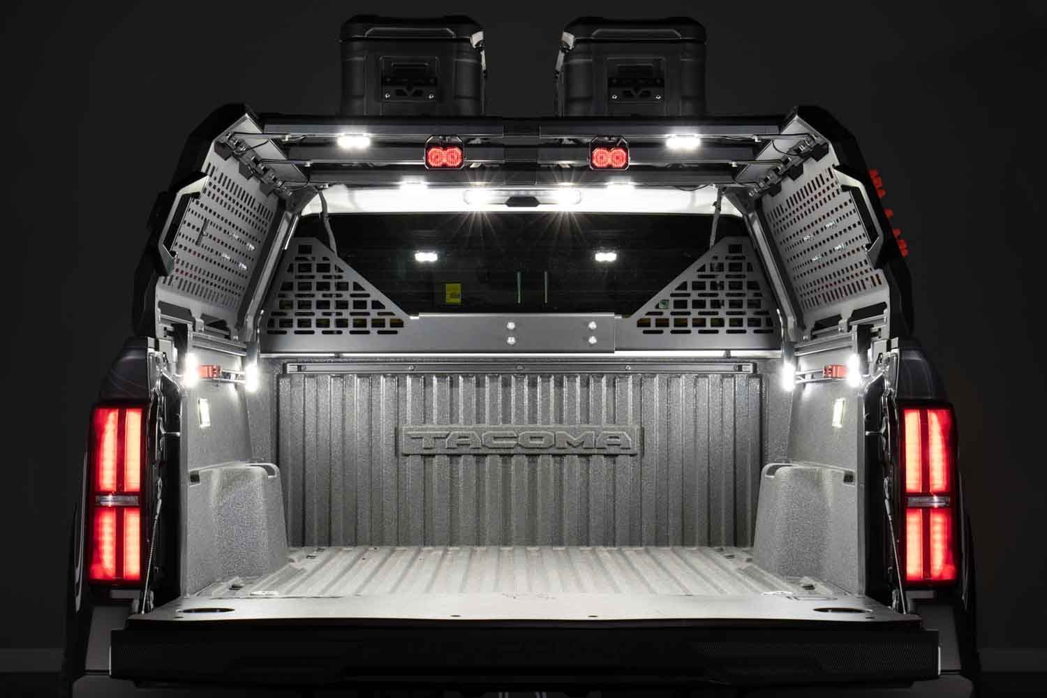
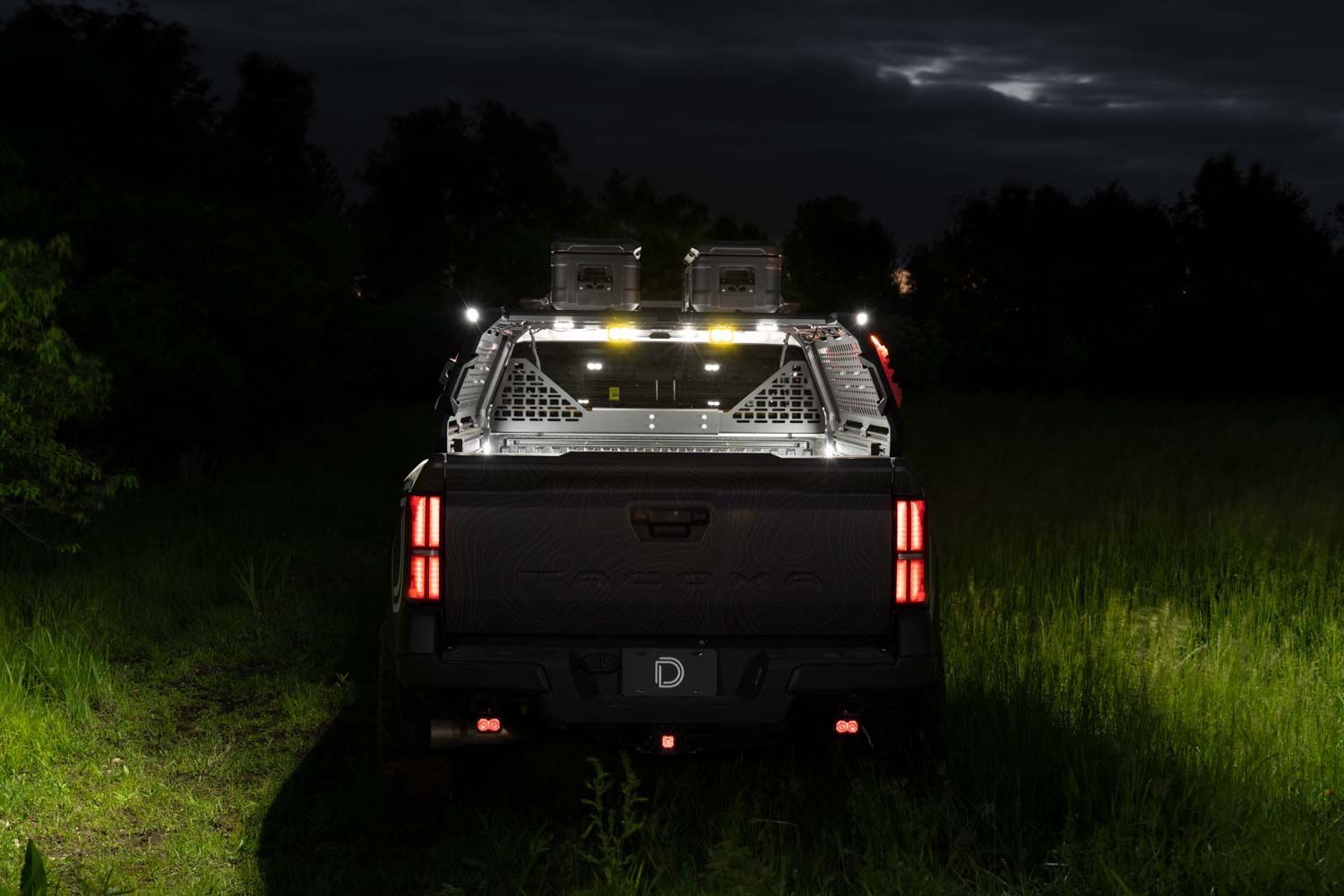
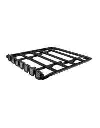
The Diode Dynamics Kuat DEK Roof Rack adds powerful, integrated lighting to the modular Kuat DEK roof rack system. This installation guide will provide you with detailed instructions on how to install the Diode Dynamics Kuat DEK Roof Rack. Watch our installation video or continue reading below for detailed instructions!
Table of Contents
- Kuat DEK Roof Rack Installation
- Installation Tools
- Installation Video
- Included Hardware
- Lighting Installation
- Wiring
- Questions About the Installation?
- Where Can I Buy the Diode Dynamics Kuat DEK Roof Rack?
Kuat DEK Roof Rack Installation
Before installing the Diode Dynamics lighting components, the Kuat DEK roof rack must be fully assembled and mounted to your vehicle.
Please follow Kuat’s official installation guide that applies to your specific mounting configuration:
Once the Kuat DEK roof rack is otherwise fully installed, return here to continue with the Diode Dynamics lighting installation.
Installation Tools
- 4mm Allen key
- 5mm Allen key
- 10mm wrench
- T20 Torx driver, lightbar applications only
Approximate installation time is 60 minutes.
Installation Video
Included Hardware
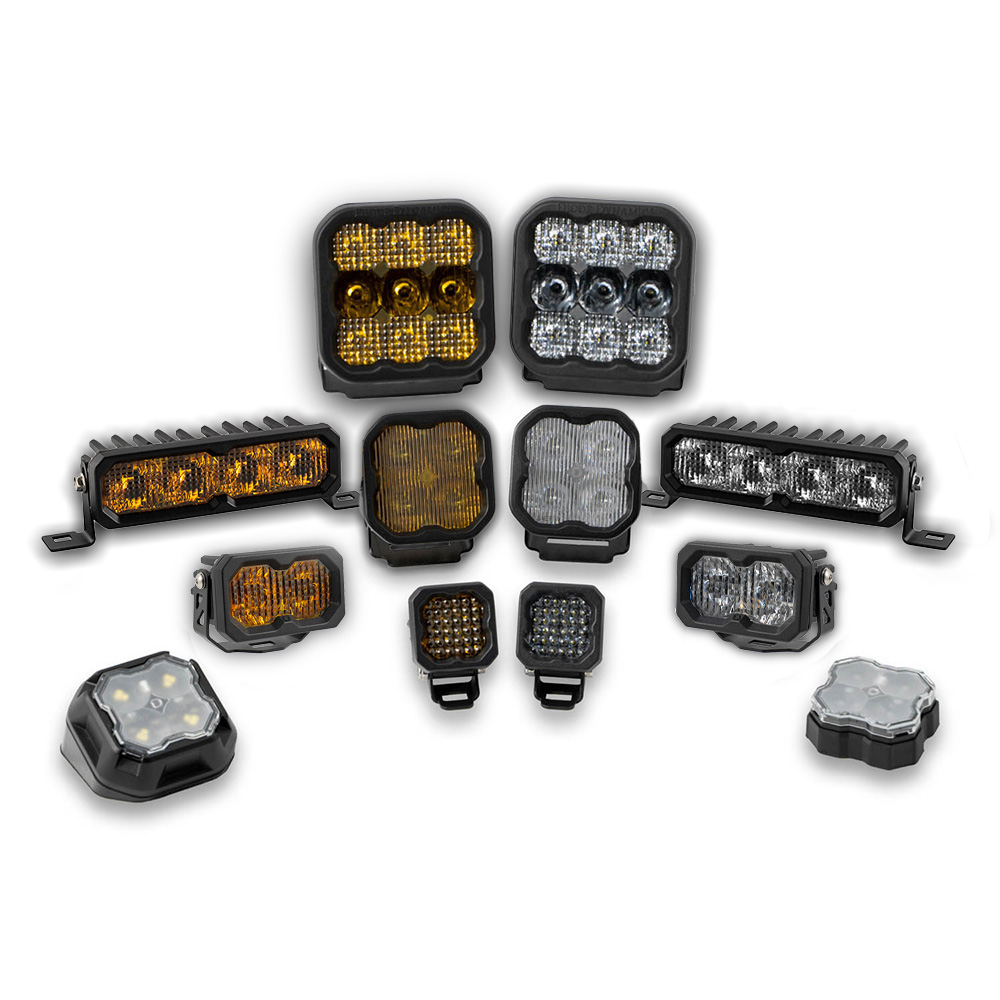
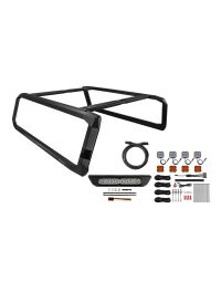
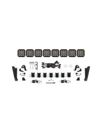
The hardware included with your kit depends on whether your lighting configuration uses SS5 CrossLink pods, an SS40 lightbar, or an SS50 lightbar. Before installation, identify the lighting configuration included with your kit and confirm that you have the matching left-hand and right-hand brackets, corner caps, fasteners, wire routing components, and any configuration-specific hardware listed below.
SS5 CrossLink applications: These kits include left-hand and right-hand SS5 light brackets, left-hand and right-hand roof rack corner caps, M6 split lock washers, M6 x 14mm button-head hex screws, black zip ties, a 1-meter wire hider with 3M adhesive, two clear 2in paint protection film pads, and a black fir-tree mounting clip for securing the CrossLink wiring connector.
SS40 lightbar applications: These kits include left-hand and right-hand lightbar brackets, left-hand and right-hand 40in lightbar corner caps, M6 split lock washers, M6 x 14mm button-head hex screws, black zip ties, a 1-meter wire hider with 3M adhesive, 10in extruded wind deflectors, and longer M4 x 35mm Torx button-head screws with nylon patch for the wind deflectors.
SS50 lightbar applications: These kits include left-hand and right-hand lightbar brackets, left-hand and right-hand roof rack corner caps, M6 split lock washers, M6 x 14mm button-head hex screws, black zip ties, a 1-meter wire hider with 3M adhesive, 10in extruded wind deflectors, and longer M4 x 35mm Torx button-head screws with nylon patch for the wind deflectors.
Lighting Installation
Step 1 — Install Corner Caps
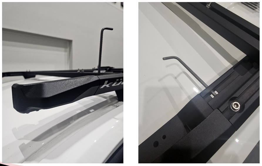
Using a 5mm Allen key, install the left-hand and right-hand corner caps onto the DEK side rails by following the Kuat instructions. SS5 CrossLink and SS50 lightbar applications use the standard roof rack corner caps, while SS40 lightbar applications use the longer 40in lightbar corner caps. Make sure the corner caps are fully seated on the side rails before continuing.
Step 2 — Attach Light Brackets
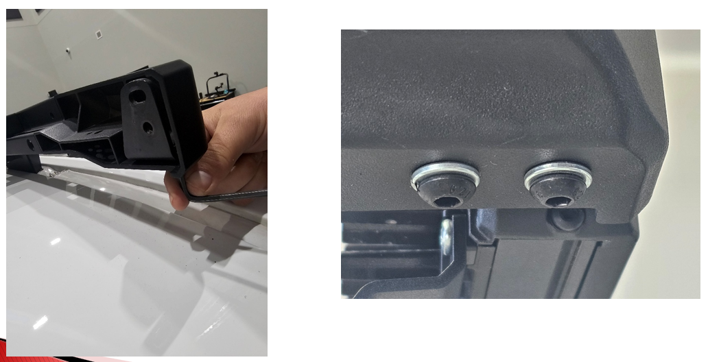
Using a 4mm Allen key, loosely install the left-hand and right-hand light brackets to the corner caps with the included M6 split lock washers and M6 x 14mm button-head hex screws. SS5 applications use the SS5 light brackets, while SS40 and SS50 applications use the lightbar brackets. Leave the hardware loose at this stage so the brackets can be adjusted when the lights are installed.
Step 3 — Assemble CrossLink Pods
If your kit includes SS5 CrossLink pods, assemble the CrossLink lightbar before mounting it to the rack. The pods can be positioned in the first or second notch on the CrossLink links, depending on whether you prefer a straight or slightly curved appearance.
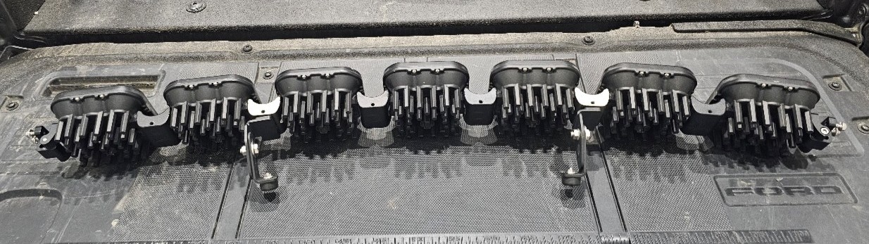
Locate the link wire harnesses and daisy-chain the pods together, starting at one end of the CrossLink assembly. There should be one fewer link wire harness than the total number of pods. When finished, leave one open connector at the end of the lightbar for the main wiring harness connection.
NOTE: SS5 CrossLink kits include standard CrossLink splitters and one terminating splitter. Use the standard splitters for the main daisy-chain connections. The terminating splitter should be installed at the end opposite the main wiring harness connection, where it connects the final two SS5 pods.
For a detailed walkthrough on assembling the SS5 CrossLink lightbar, refer to our SS5 CrossLink assembly video on YouTube.
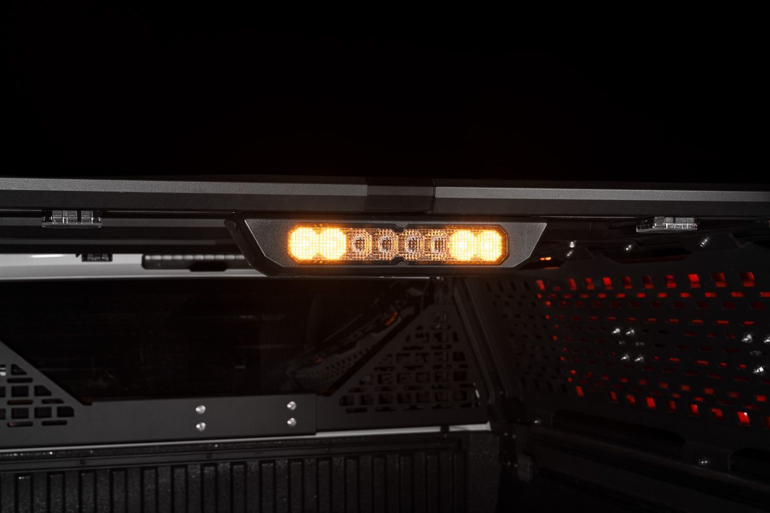
Step 4 — Mount the Lights
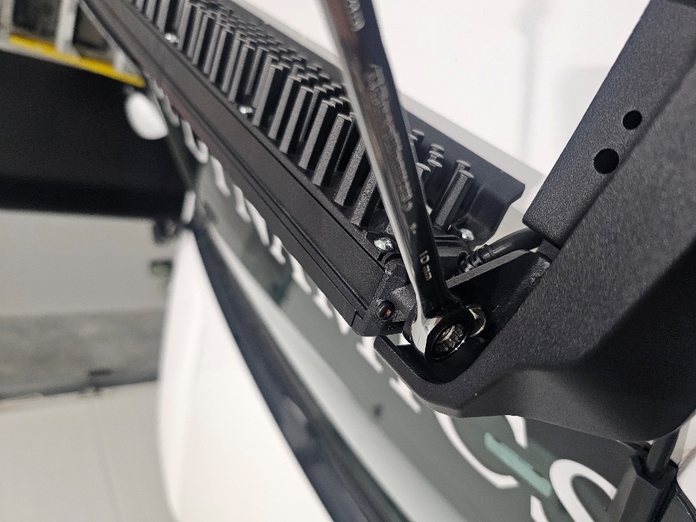
Using a 10mm wrench, install the SS5 CrossLink assembly or Stage Series lightbar onto the light brackets with the light’s included mounting hardware. Center the light assembly in the rack opening, adjust the angle as needed, and then tighten the M6 x 14mm button-head screws from the previous step. Confirm that the light assembly and brackets are secure before continuing.
Step 5 — Install Wind Deflectors
For SS40 and SS50 lightbar applications, install the included 10in extruded wind deflectors to help reduce wind vibration and noise. Using a T20 Torx driver, remove the bottom three screws on the back of each 10in lightbar segment. Place the wind deflector against the back of the lightbar segment, then secure it using the provided longer M4 x 35mm Torx button-head screws with nylon patch. Tighten the screws to 10–15 in-lbs.

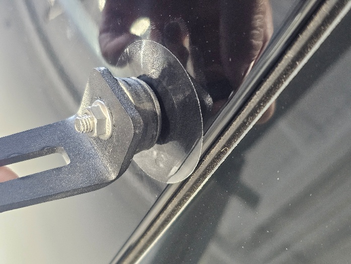
Step 6 — Install Paint Protection and Mounting Clip
For SS5 CrossLink applications, clean the painted roof surface where the CrossLink support bumpers will contact the vehicle. Once the surface is free of dirt and debris, apply the two clear 2in paint protection film pads directly to the paint in those contact areas. These pads help protect the painted surface from the CrossLink support bumpers.
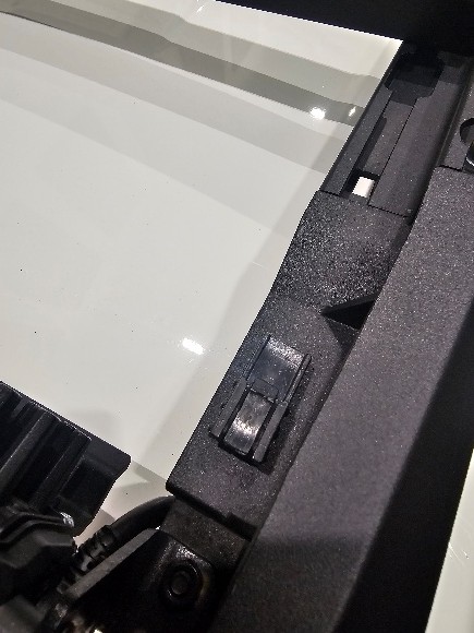
Install the included black fir-tree mounting clip into one of the corner caps, then secure the CrossLink wiring connector to the clip. This keeps the connector supported near the corner cap and prevents it from hanging loose after the harness is connected.

Wiring
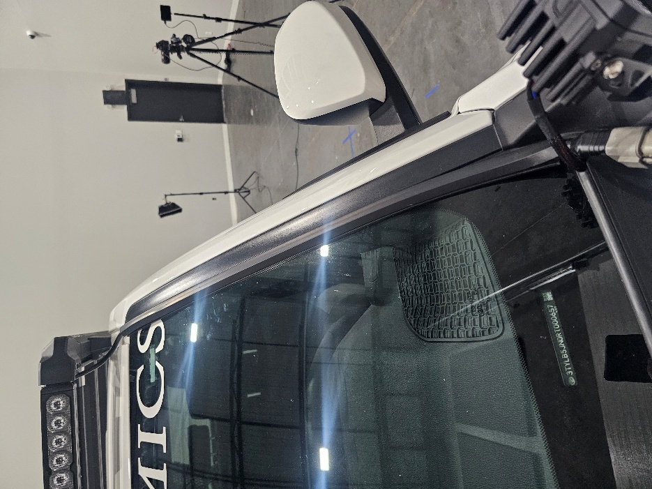
Step 7 — Route the Wiring
Connect the main harness to the light assembly. Determine whether you want to route the wiring down the driver-side or passenger-side windshield, then clean the windshield edge where the 1-meter adhesive wire hider will be installed. Peel the backing from the wire hider and apply it along the windshield edge, using it to guide the wiring cleanly down into the engine bay.
Use the included black zip ties to secure the wiring along the rack and in the engine bay. Keep all wiring away from sharp edges, moving parts, and areas with excessive heat buildup.
Step 8 — Connect Power
Complete the wiring using standard Diode Dynamics wiring practices. Route the harness to the battery, following the vehicle manufacturer’s wiring path whenever possible. Connect the black ground wire to the negative battery terminal, then connect the red power wire to the positive battery terminal.
Determine a suitable location to mount the switch and route the switch wiring to that location. This may require routing the wiring through the vehicle’s firewall. If needed, unplug the toggle switch from the harness to make routing easier, drill an appropriately sized hole for the switch, reconnect the switch wiring, and mount the switch securely.
Once power and ground are connected, test the lights to verify proper operation. After confirming that all installed lights operate correctly, secure any remaining wiring slack, relay, fuse holder, or excess harness length away from heat, sharp edges, and moving parts.
The installation is now complete. Enjoy your new Diode Dynamics Kuat DEK Roof Rack!
Questions About the Installation?
If you have any questions about installing the Diode Dynamics Kuat DEK Roof Rack, contact us via our support page.
Where Can I Buy the Diode Dynamics Kuat DEK Roof Rack?
If you're ready to upgrade your vehicle with the Diode Dynamics Kuat DEK Roof Rack, visit DiodeDynamics.com or use our Dealer Locator to find a dealer near you.
Want to know more about Diode Dynamics products? Visit DiodeDynamics.com and subscribe to our newsletter for new product releases and more!
This Installation Guide is for the following SKU: DD8490, DD8491, DD8492, DD8493, DD8494, DD8495, DD8496, DD8497, DD8498, DD8499, DD8500, DD8501, DD8502, DD8503, DD8504, DD8505, DD8506, DD8507, DD8508, DD8509, DD8510, DD8511, DD8512, DD8513, DD8514, DD8515, DD8516, DD8517, DD8518, DD8519
Share This Post