


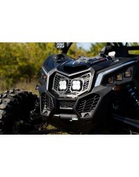
The SS10 LED Shock Mount Kit for 2017-2025 Can-Am Maverick X3 adds a clean, secure mounting solution for an SS10 LED Light Bar, providing powerful forward-facing illumination on the trail. This installation guide will provide you with detailed instructions on how to install the SS10 LED Shock Mount Kit for 2017-2025 Can-Am Maverick X3. Continue reading for step-by-step instructions below!
Table of Contents
Installation Tools
- 10mm wrench
- 13mm wrench
- 10mm socket
- 13mm socket
- 18mm socket
- Ratchet
- Wire running tool
- Tape
Time Required: 90-120 minutes
Installation Instructions
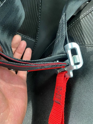
Step 1 — Remove passenger seat belt
Disconnect the seatbelt from the base of the passenger seat by pulling the looped end through and out of the harness.
Step 2 — Remove passenger seat
Adjust the passenger seat all the way forward by pulling the lever towards you and pushing the seat up to access the rear mounting hardware.
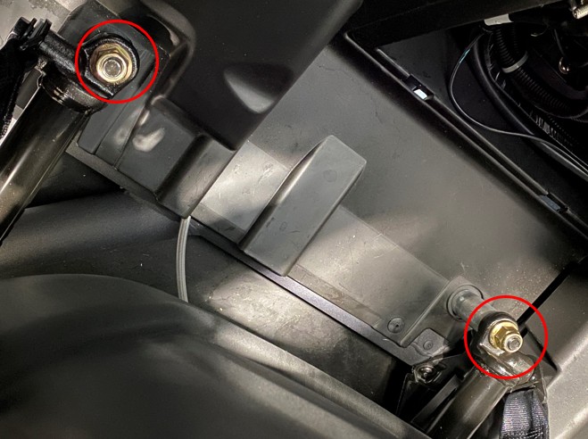
Step 3 — Remove rear locking nuts
With the seat pushed forward, reach behind the seat and use an 18mm socket and ratchet to remove the two rear gold locking nuts.
Step 4 — Remove front seat fasteners
Adjust the seat all the way back to access the front mounting points. Using a 13mm wrench and a 13mm socket with a ratchet, remove the two 13mm bolts and locking nuts. Carefully lift the seat up and out of the vehicle once all fasteners are removed.
Step 5 — Disconnect the battery
Using a 10mm socket or wrench, disconnect the positive (red) battery lead to prevent accidental shorts while installing the relay. Secure the lead away from the terminal.
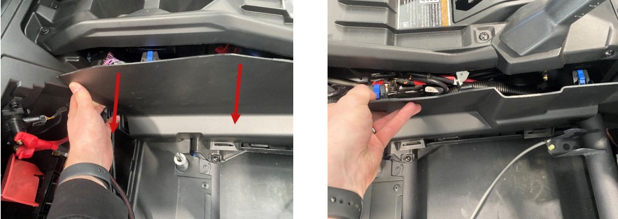
Step 6 — Remove passenger side console panel (rear)
To access the busbar, remove the passenger side console panels. Carefully pull away the top-left corner to release the clips, then work your way toward the front until the panel is fully released. Set it aside for reinstallation later.
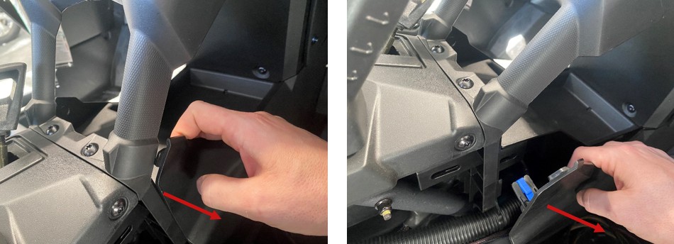
Step 7 — Remove passenger side console panel (front)
Repeat the previous step on the most forward passenger side console panel. Set it aside for reinstallation later.
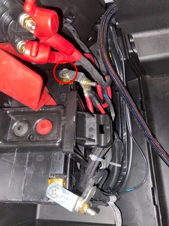
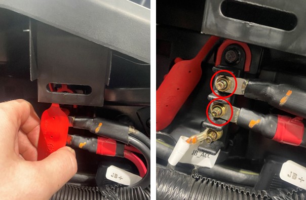
Step 8 — Access the busbar
Peel back the rubber protective covering to access the busbar. Using a 10mm socket and ratchet, loosen the top two bolts to prepare for relay installation.
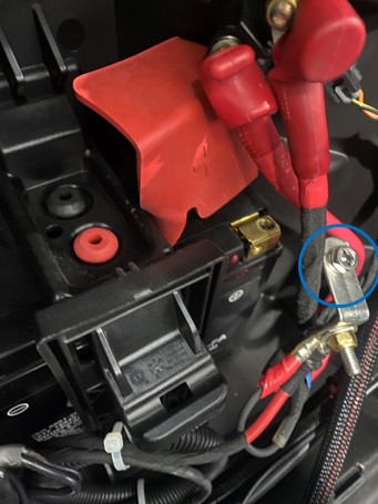
Step 9 — Install wiring harness
Install the wiring harness relay at the busbar mounting location, then prepare the power and ground leads for connection.
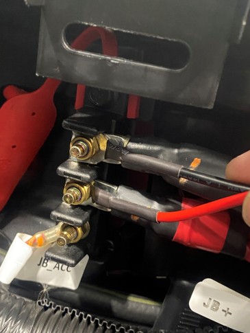
Step 10 — Connect power and ground, then route harness
Slide the black wire lead into the negative terminal and the red wire lead into the positive terminal. Using a 10mm socket and ratchet, tighten both terminals. Reattach the rubber protector and tuck the relay into an open area so you can reinstall the panels later. Then, keeping the harness away from moving or hot parts, run the DT connector and switch wiring up through the center console behind the panels and pass both leads over to the driver’s side floorboard.
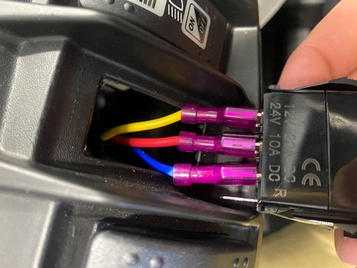
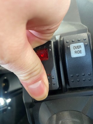
Step 11 — Route switch wire to desired location
Choose your switch mounting location. Route the switch leads to the desired location and connect the switch using the wiring pattern shown in the guide. Do not fully push the switch into the housing until you’ve confirmed proper function.
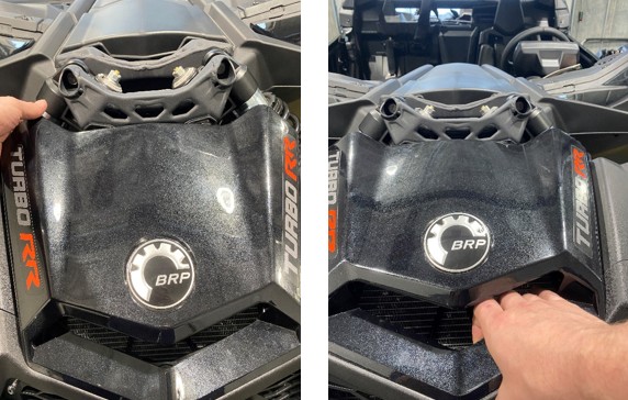
Step 12 — Remove the hood
With a firm tug, pull the top-left side of the hood up and away from the vehicle. Work your way around until all five attachment points are released, then set the hood aside for reinstallation later.
Step 13 — Route Deutsch connector through the firewall
From the driver’s side floorboard, run your wire running tool through the firewall, leaving the near side on the floorboard. Tape the Deutsch connector to the end of the tool, then move to the front of the vehicle and pull the harness through.
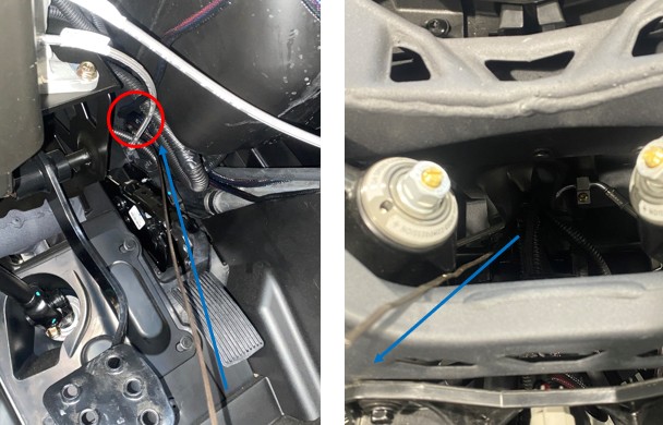
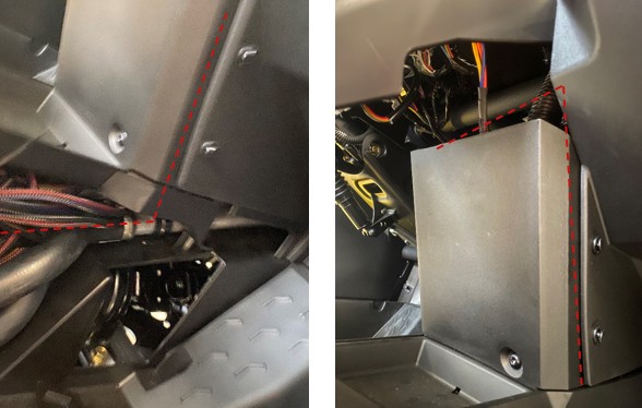
Step 14 — Route connector through center access point
With the connector pulled through, route the Deutsch connector through the center access point as shown.
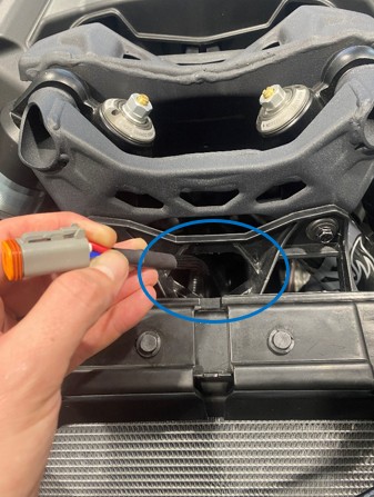
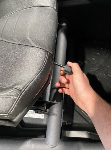
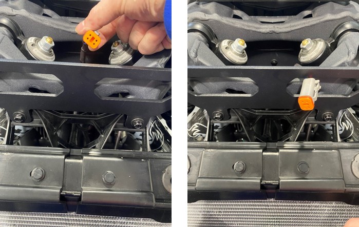
Step 15 — Remove shock mount bolts
Using a 10mm socket, ratchet, and a 10mm wrench, remove the two factory shock mount bolts shown. Set the hardware aside for reuse.
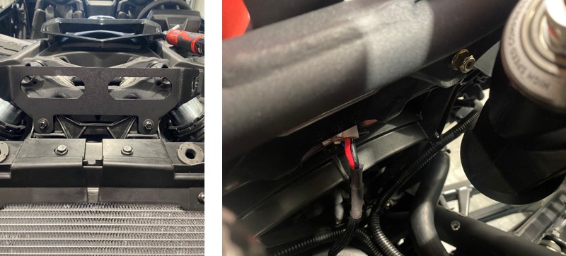
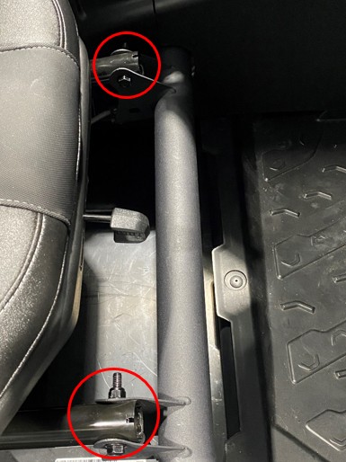
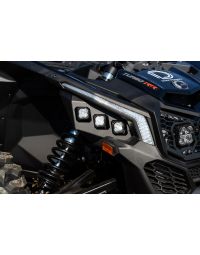
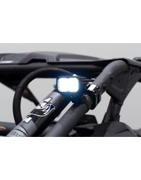
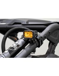
Step 16 — Install shock mount light bar bracket
Reuse the factory hardware by placing the bolts (with washers) through the bracket and mounting it to the vehicle. Finger-tighten the nuts behind the bracket, then tighten fully using a 10mm wrench, 10mm socket, and ratchet.
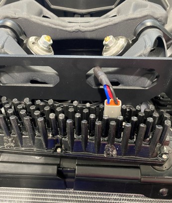
Step 17 — Prepare harness at the bracket area
Take the harness you routed through the firewall and insert it through the gap on the right side near the bracket area.
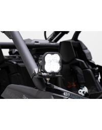
Step 18 — Plug connector into light bar
Plug the Deutsch connector into the light bar and confirm you hear/feel a click when the lock engages.
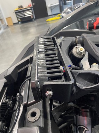
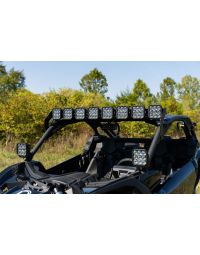
Step 19 — Install and aim the light bar
Place the light bar into the bracket with the connector oriented toward the driver side. Align the middle mounting holes on the light bar to the bracket mounting points and finger-tighten the included bolts. Reconnect the battery, test switch function, aim the light bar to the desired position, and tighten all mounting hardware securely.
Step 20 — Secure wiring and reassemble
Push the switch into the housing, secure any excess wire inside the center console, and reinstall the passenger side console panels and passenger seat by reversing the removal steps.
The installation is now complete. Enjoy your new SS10 LED Shock Mount Kit for 2017-2025 Can-Am Maverick X3!
Questions About the Installation?
If you have any questions about installing the SS10 LED Shock Mount Kit for the 2017-2025 Can-Am Maverick X3, contact us via our support page.
Where Can I Buy the SS10 LED Shock Mount Kit for the 2017-2025 Can-Am Maverick X3?
If you're ready to upgrade your 2017-2025 Can-Am Maverick X3 with the SS10 LED Shock Mount Kit, visit DiodeDynamics.com or use our Dealer Locator to find a dealer near you.
Want to know more about Diode Dynamics products? Visit DiodeDynamics.com and subscribe to our newsletter for new product releases and more!
This Installation Guide is for the following SKU: DD8292, DD8293, DD8311, DD8312, DD8294, DD8295, DD8313, DD8314, DD8296, DD8297, DD8315, DD8316, DD8291P
Share This Post