


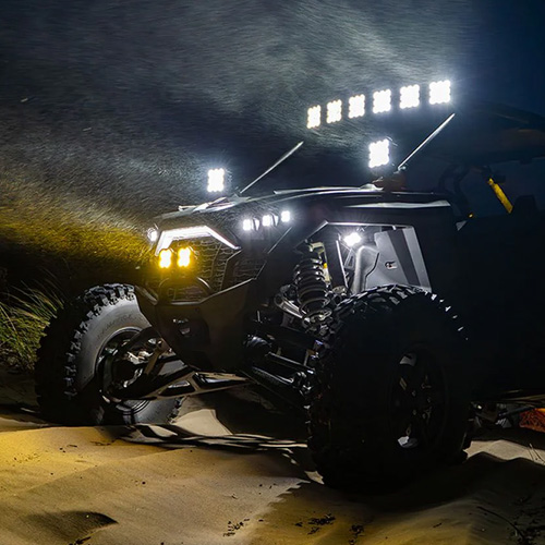

The SS10 LED Chase Light adds high-output brake, reverse, and programmable chase functionality for increased visibility and safety. This installation guide will provide you with detailed instructions on how to install the SS10 LED Chase Light. Continue reading for step-by-step instructions below!
Table of Contents
Installation Tools
- Basic hand tools
- Drill and drill bits, if required for your mounting location
- Wire strippers and crimpers
- Soldering tools or electrical connectors
- Multimeter
- Zip ties
Installation Instructions
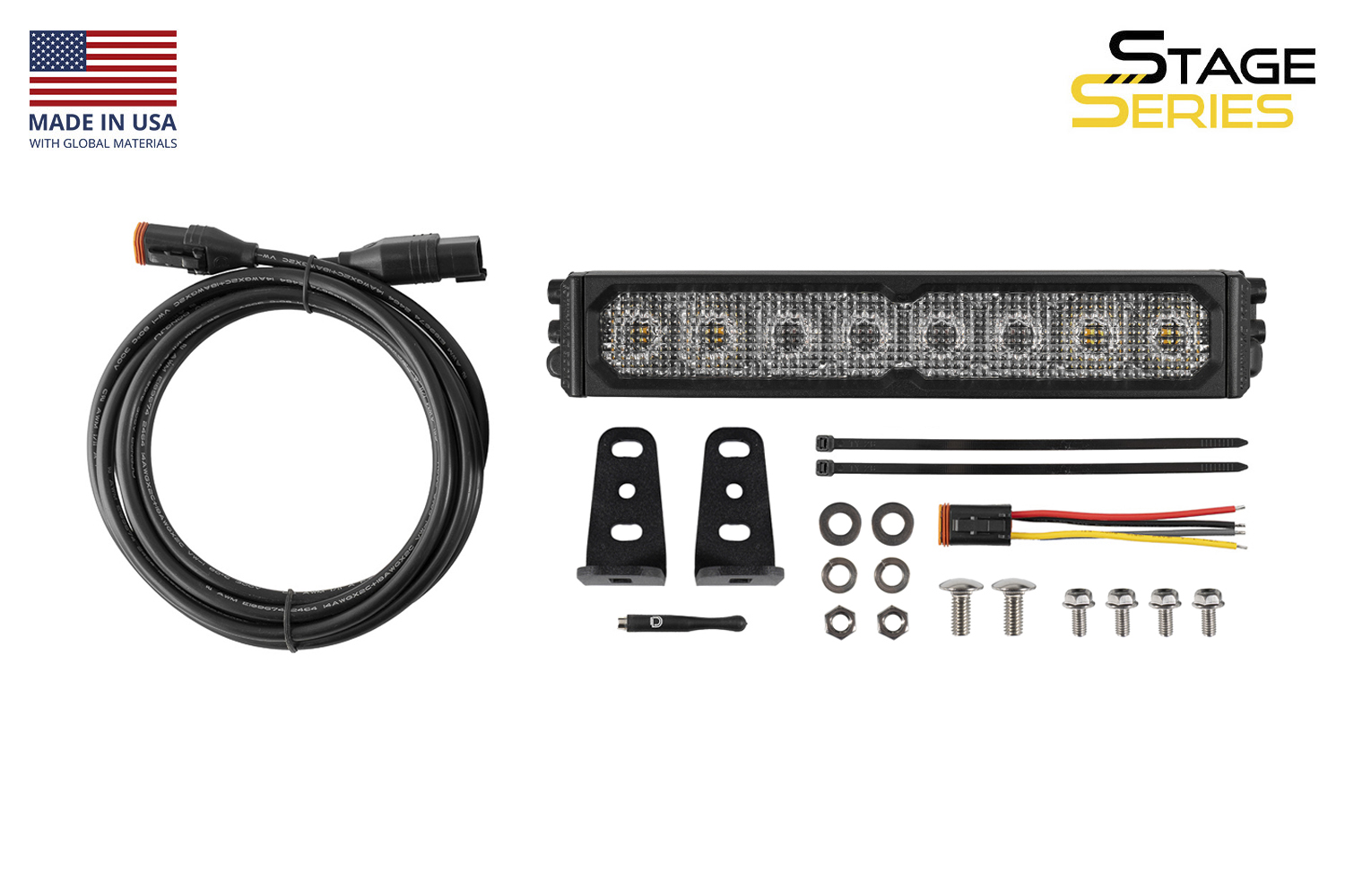
Step 1 — Unpack and Identify Components
Begin by unpacking the SS10 LED Chase Light. The kit includes the SS10 LED Chase Light, mounting brackets, hardware, a 3m extension wire, wiring pigtail, and magnet tool tool for SmartTap Programming.
Step 2 — Choose a Mounting Location
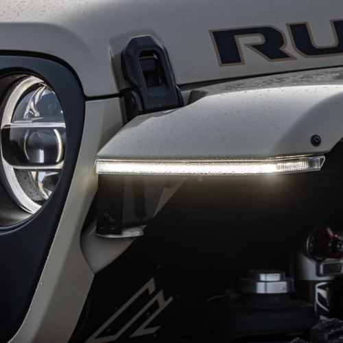
Select a suitable mounting location for the light. Common mounting points include rear bumpers, roof racks, chase racks, and other flat surfaces with a clear rear-facing line of sight. Make sure the chosen location allows room for the brackets, hardware, and wire routing.
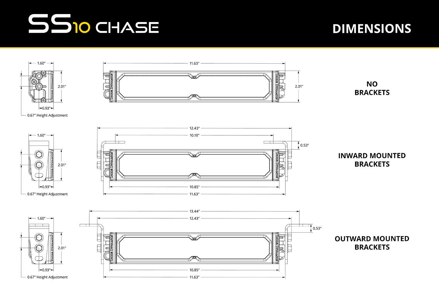
Step 3 — Attach the Mounting Brackets
Install the included L-brackets onto the SS10 LED Chase Light using the supplied hardware. Leave the hardware slightly loose so you can adjust the angle and final position during installation.
Step 4 — Mount the Light and Route the Wiring
Secure the light to your chosen mounting surface using appropriate hardware. Once mounted, route the wiring toward your signal sources and switch location. Avoid sharp edges, excessive heat, and moving components, and secure the wiring along the way with zip ties.
Please note: The included 3m extension and pigtail provide initial connectivity, but additional wiring or DT extensions may be required to reach your vehicle’s signal sources or switch panel, especially if routing wires to the front of the vehicle. When extending wiring, we recommend using 14-gauge wire to match the included harness.
Step 5 — Connect Function Input Wires
The SS10 LED Chase Light uses signal-based inputs instead of a traditional relay harness or direct battery connection. Connect the red wire to your vehicle’s brake light signal, the blue wire to your reverse or cargo light signal, and the black wire to a solid chassis ground.
This setup allows the brake and reverse functions to activate automatically when those factory signals are triggered.
Step 6 — Connect the Chase Function
Connect the yellow wire to a toggle switch, switch panel, or auxiliary controller. When 12V is applied to this wire, the chase function will activate. This allows you to control the chase/strobe feature independently from the factory brake and reverse circuits.
Step 7 — Optional: Configure Manual Control
If desired, any of the light’s input wires can be connected to a manual switch or control system instead of an OEM signal. For example, the blue wire can be connected to a switch for use as a cargo or work light, and the red wire can be connected to a controller for custom activation.
This gives you flexibility to configure the SS10 LED Chase Light for your specific application.
Step 8 — Optional: Modify Pins for a 7-Pin Harness
If you are integrating the light with a standard 7-pin trailer harness (RV blade style), you can access the following signals:
Pin 4 (typically labeled “Stop/Left Turn”): Brake signal
Pin 7 (center pin, typically labeled “Reverse”): Reverse signal
Wire colors may vary by vehicle, so always verify function with a multimeter before making connections. Use proper pin extraction tools if repinning is required.
Step 9 — Test All Functions
Once all wiring is complete, test the brake, reverse, and chase functions to verify proper operation. Confirm that each input wire activates the intended function and make any final bracket adjustments before tightening all hardware.
The installation is now complete. Enjoy your new SS10 LED Chase Light!
Wiring Guide
The SS10 LED Chase Light uses signal-based inputs to control each function. No relay harness or direct battery connection is required.
Red Wire: Brake signal input
Blue Wire: Reverse or cargo light input
Yellow Wire: Chase activation from a switch or controller
Black Wire: Ground
Each function is activated when 12V is applied to the corresponding input wire. The brake and reverse functions are commonly tied into OEM vehicle signals, while the chase function is typically connected to a toggle switch or switch panel.
Only a 3m extension and pigtail are included with this kit. Additional wiring, connectors, or DT extensions may be required depending on your installation and routing needs. For best performance and reliability, use 14-gauge wire when extending any of the circuits.
SmartTap Programming
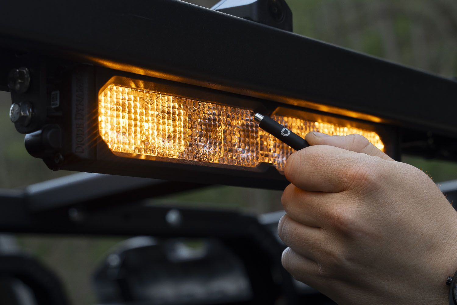
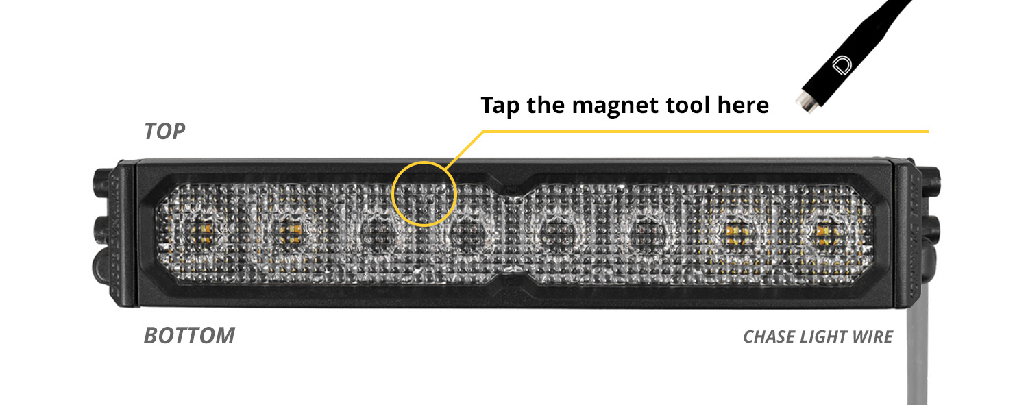
The SS10 LED Chase Light features SmartTap Programming, which allows you to scroll through the available brake and chase patterns using the included magnet tool tool.
To program a function, apply power to the wire for the function you want to configure. With that function powered on, place the magnet tool near the built-in hall effect sensor located between the first and second optic from the center of the light. Each pass with the magnet tool will advance to the next available pattern.
The chase function includes 20 available strobe patterns, while the brake function includes 3 available patterns. Continue cycling until you reach your desired setting. The selected pattern will be retained after power is removed.
Please note that the SS10 LED Chase Light does not include a separate programming indicator, so be sure to observe the light output as you scroll through the available patterns.
Questions About the Installation?
If you have any questions about installing the SS10 LED Chase Light, contact us via our support page.
Where Can I Buy the SS10 LED Chase Light?
If you're ready to upgrade your vehicle with the SS10 LED Chase Light, visit DiodeDynamics.com or use our Dealer Locator to find a dealer near you.
Want to know more about Diode Dynamics products? Visit DiodeDynamics.com and subscribe to our newsletter for new product releases and more!
This Installation Guide is for the following SKU: DD8931

Share This Post