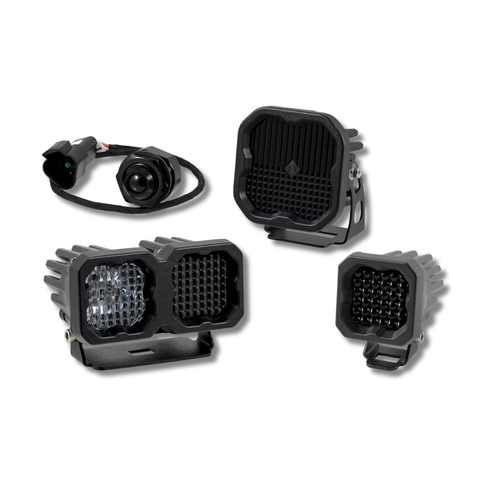
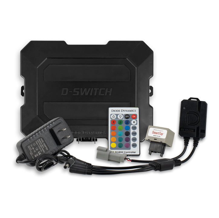



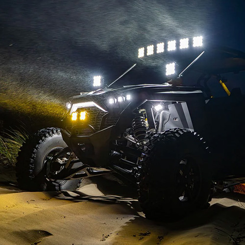
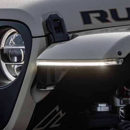

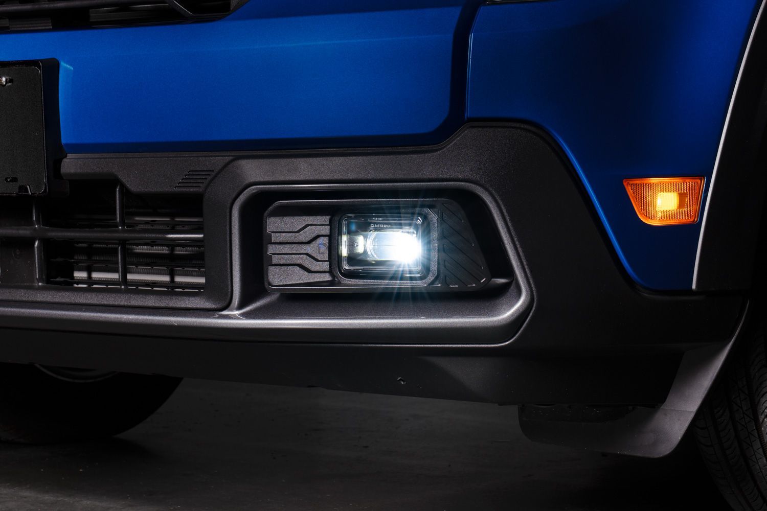
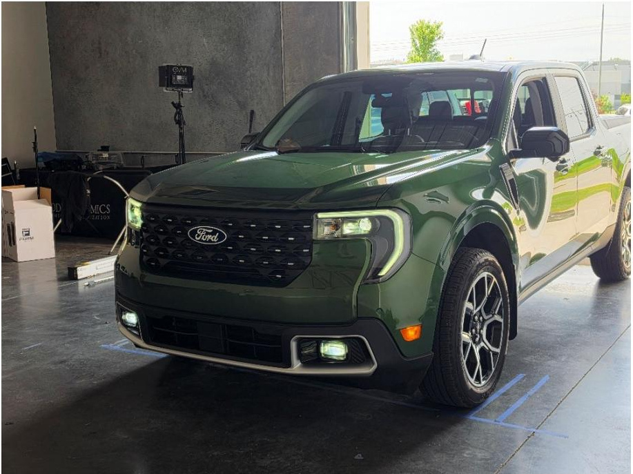
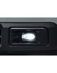
The Elite Series Add-On Fog Lamp Kit for the 2025-2027 Ford Maverick adds factory-style fog lighting for improved forward visibility in fog, dust, snow, and rain, along with integrated amber backlighting. This installation guide will provide you with detailed instructions on how to install the Elite Series Add-On Fog Lamp Kit for the 2025-2027 Ford Maverick. Continue reading for step-by-step instructions below!
Table of Contents
- Installation Video
- Installation Tools
- Installation Instructions
- Questions About the Installation?
- Where Can I Buy the Elite Series Add-On Fog Lamp Kit for the 2025-2027 Ford Maverick?
Installation Video
Installation Tools
Installation Time: Approximately 2 hours.
- Pry or trim tool
- 7mm socket
- 8mm socket
- 10mm socket
- 13mm socket
- 10mm wrench
- 13mm wrench
- T15 Torx bit
- T30 Torx bit
- Long Phillips screwdriver
- Rotary tool with cutting disc
- Painter's tape
- Knife or scissors
- Drill with 3/8" bit
- Silver marker
- Padded work surface or blanket
Installation Instructions
Note: Steps identified as hybrid-only apply only to hybrid models. Non-hybrid models should skip those steps and follow the non-hybrid connection in Step 22.
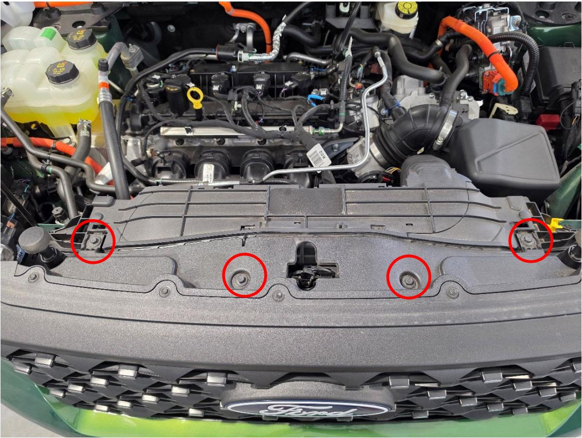
Step 1 — Remove upper bumper screws
Open the hood. Along the top edge of the front bumper, use a 10mm socket to remove the four screws shown. Set the hardware aside for reinstallation.
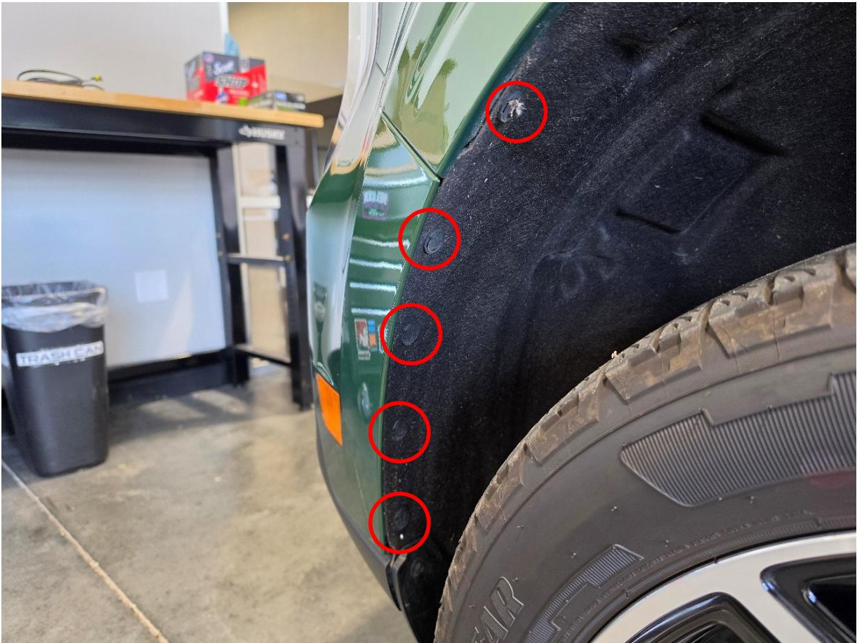
Step 2 — Remove fender liner push pins
Use a pry tool to remove the five push pins securing the front section of the fender liner. Repeat this process on the opposite side of the vehicle.
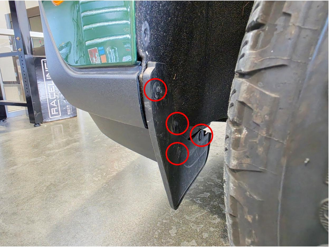
Step 3 — Remove splash guard fasteners
At the front splash guard, use a 7mm socket to remove three screws, then use a pry tool to remove one push pin. Repeat this process on the opposite side.
Step 4 — Remove lower bumper screws
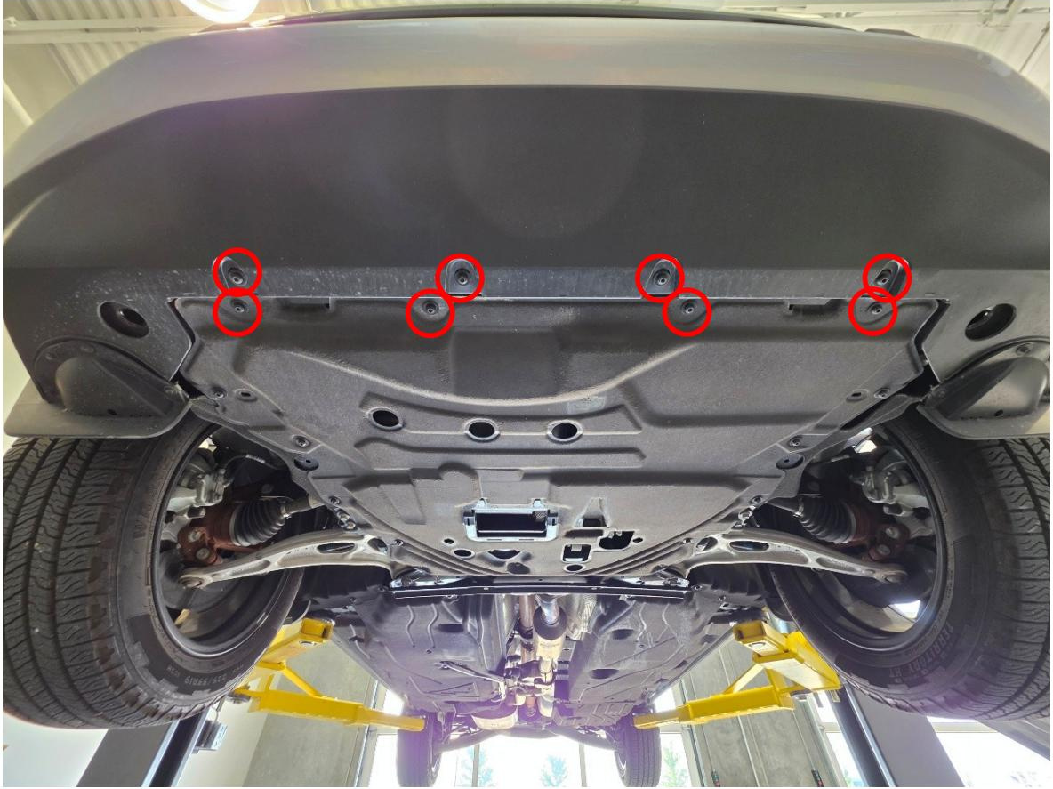
From underneath the front bumper, use a T30 Torx bit to remove the eight screws spanning the lower edge of the bumper assembly.
Step 5 — Remove inner fender bolts
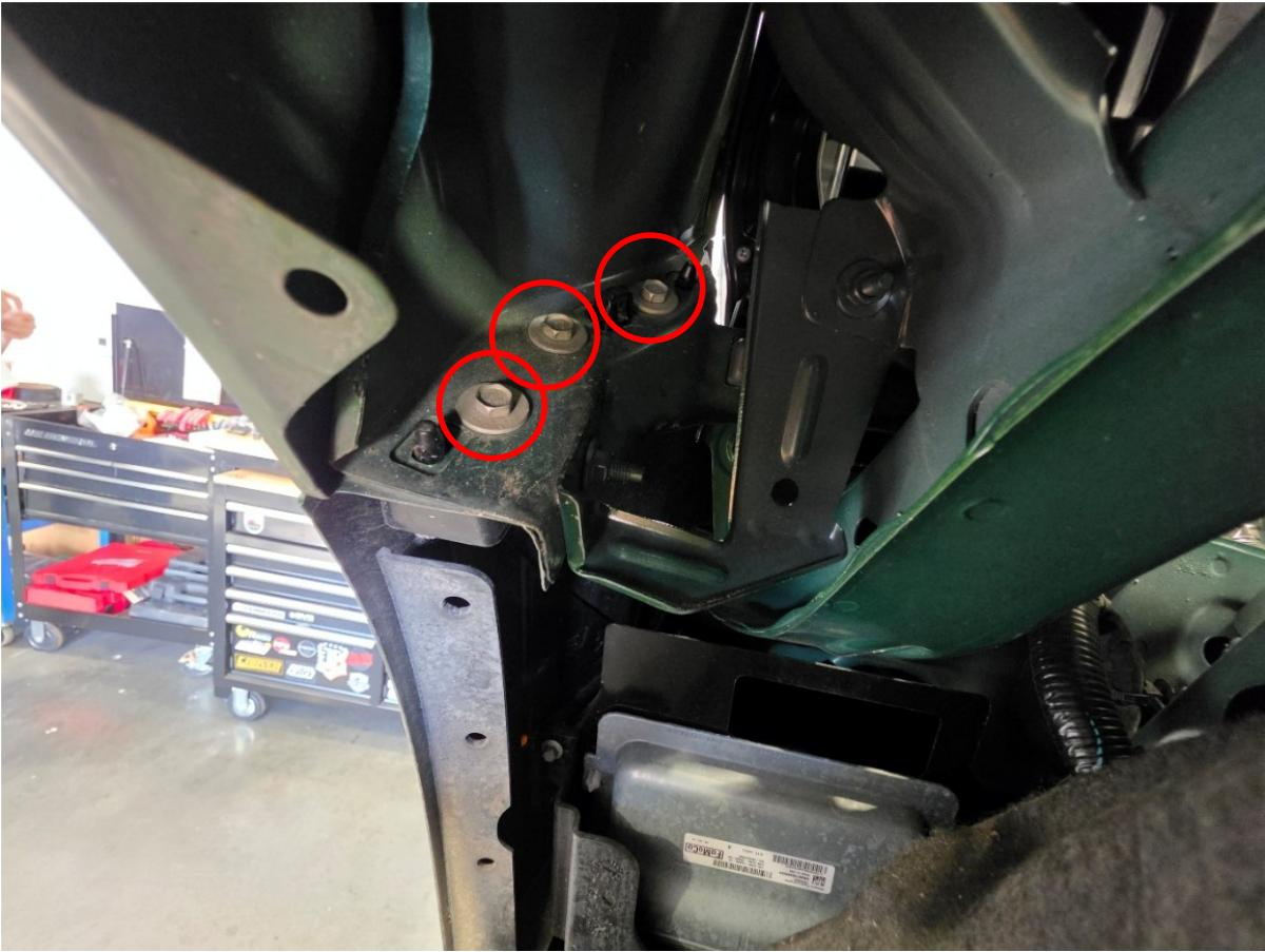
Pull the fender liner away from the bumper. Use a 10mm wrench to remove the three bolts inside the fender well that secure the bumper cover. Repeat this process on the opposite side.
Step 6 — Release bumper corners
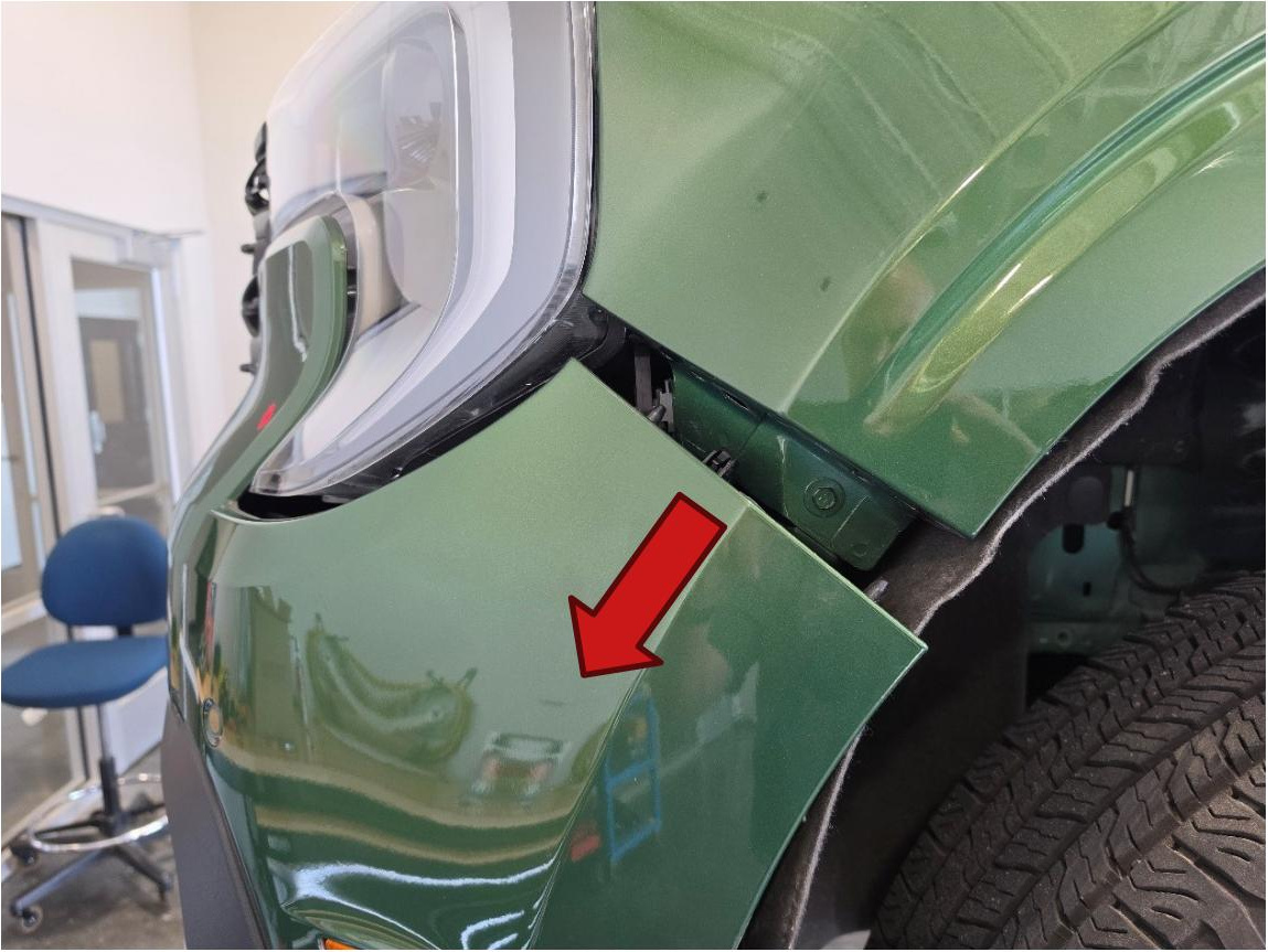
Starting at the wheel opening, carefully pull the bumper cover downward and outward to separate it from the front quarter panel. Repeat this process on the opposite side, working slowly to avoid damaging the retaining tabs.
Step 7 — Disconnect the factory bumper harness
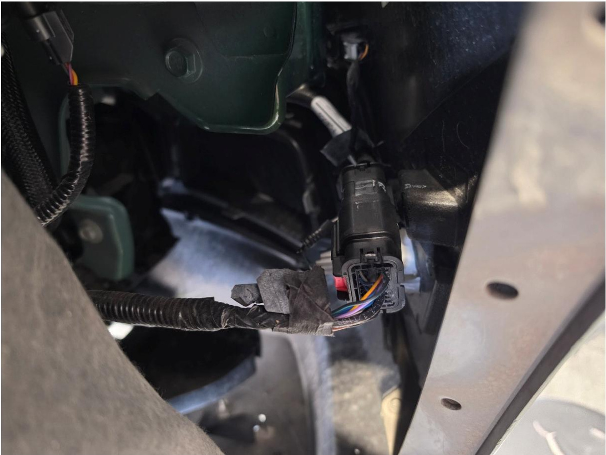
Inside the passenger-side wheel well, locate the factory wiring connector attached to the bumper and disconnect it before pulling the bumper farther away from the vehicle.
Step 8 — Release the upper bumper tabs
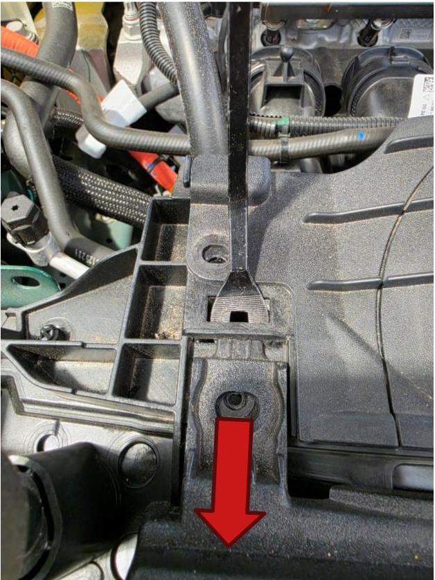
At the upper bumper tab shown, use a pry tool to apply slight upward pressure to the locking tongue while pulling the bumper rearward. Release the remaining upper tabs, then carefully remove the bumper assembly from the vehicle.
Step 9 — Remove the hybrid speaker
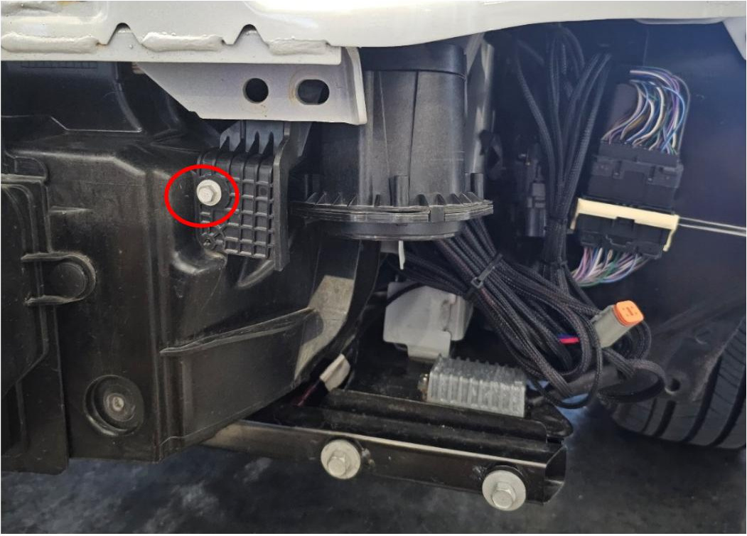
Hybrid models only: Place the removed bumper on a padded surface. Locate the hybrid speaker behind the bumper and use a 10mm socket to remove its mounting screw.
Step 10 — Transfer the hybrid speaker to the relocation bracket
Hybrid models only: Use a T15 Torx bit to remove the speaker from its factory bracket. Attach the speaker to the included relocation bracket using the factory fasteners.

Step 11 — Reinstall the relocated hybrid speaker
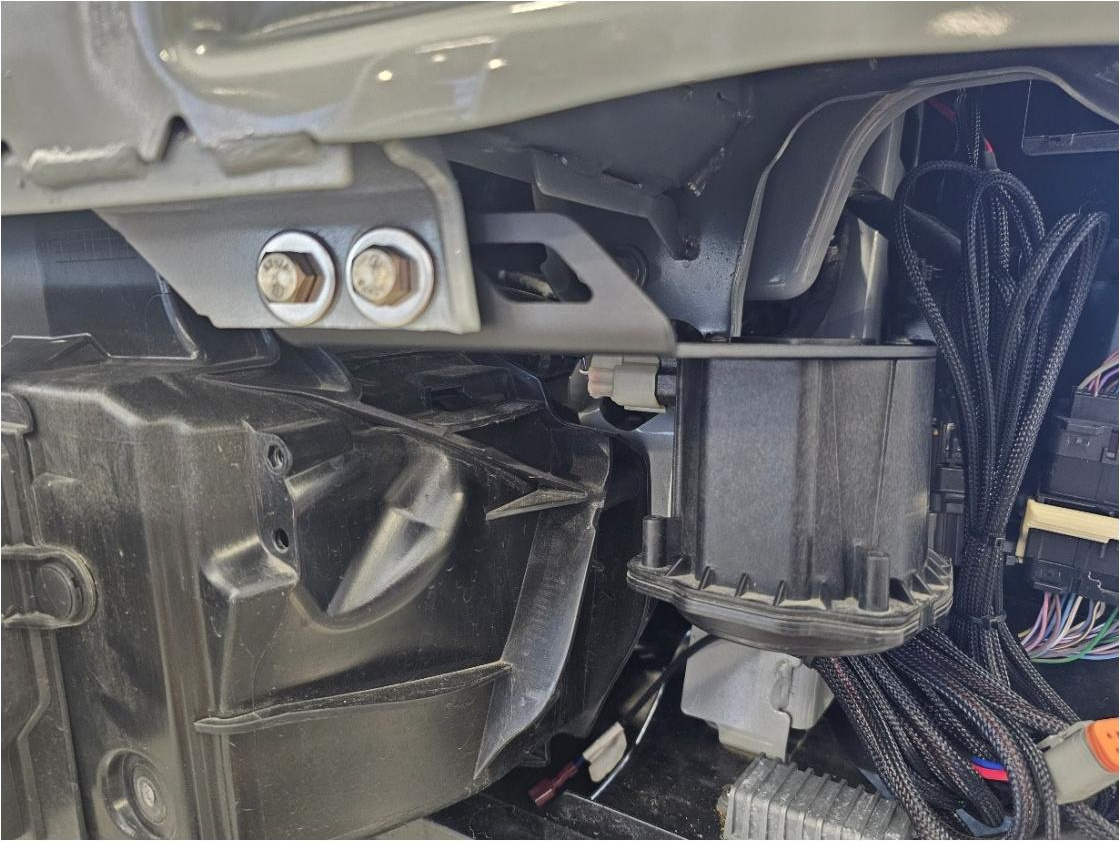
Hybrid models only: Position the relocated speaker behind the bumper. Use a 13mm wrench and 13mm socket to secure the bracket with the included bolt, nut, washers, and split lock washer.
Step 12 — Release the lower surround clips
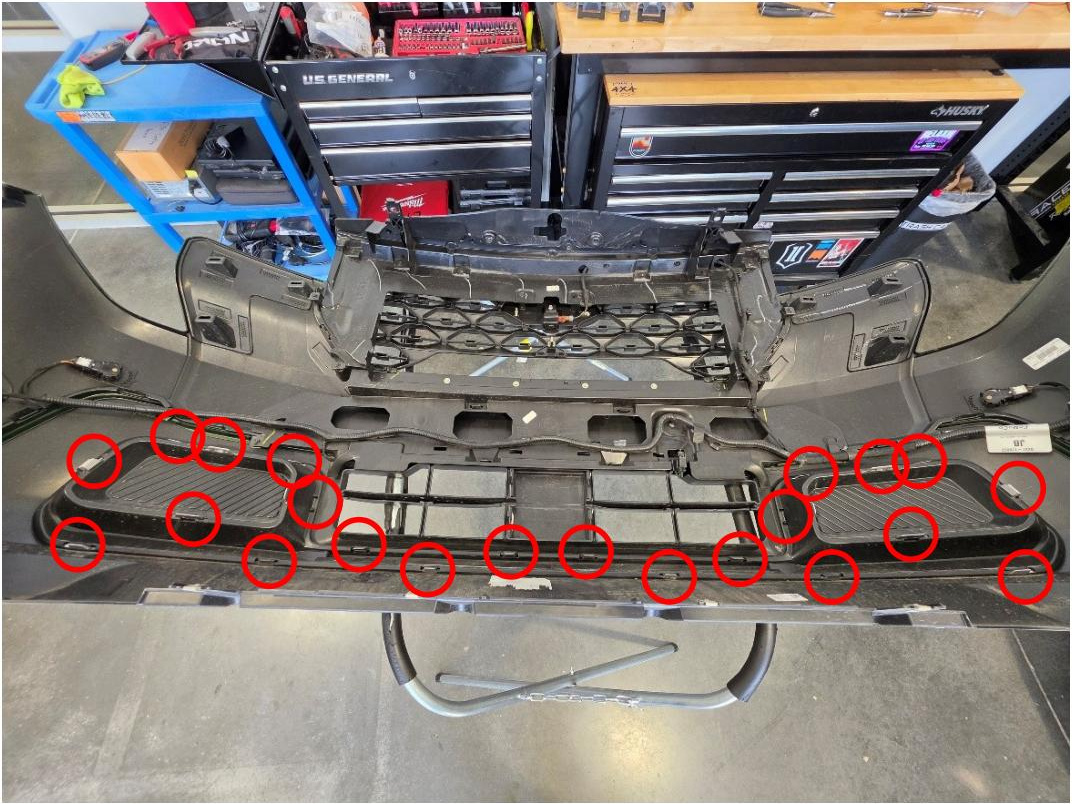
With the front bumper on a padded surface, release the 24 clips around the lower cover to separate the aesthetic surround. Removing this surround is optional, but doing so reduces the risk of damaging it during the cutting process.
Step 13 — Remove the aesthetic surround
Lift the aesthetic surround away from the front of the bumper and place it in a safe location until it is ready to be reinstalled.
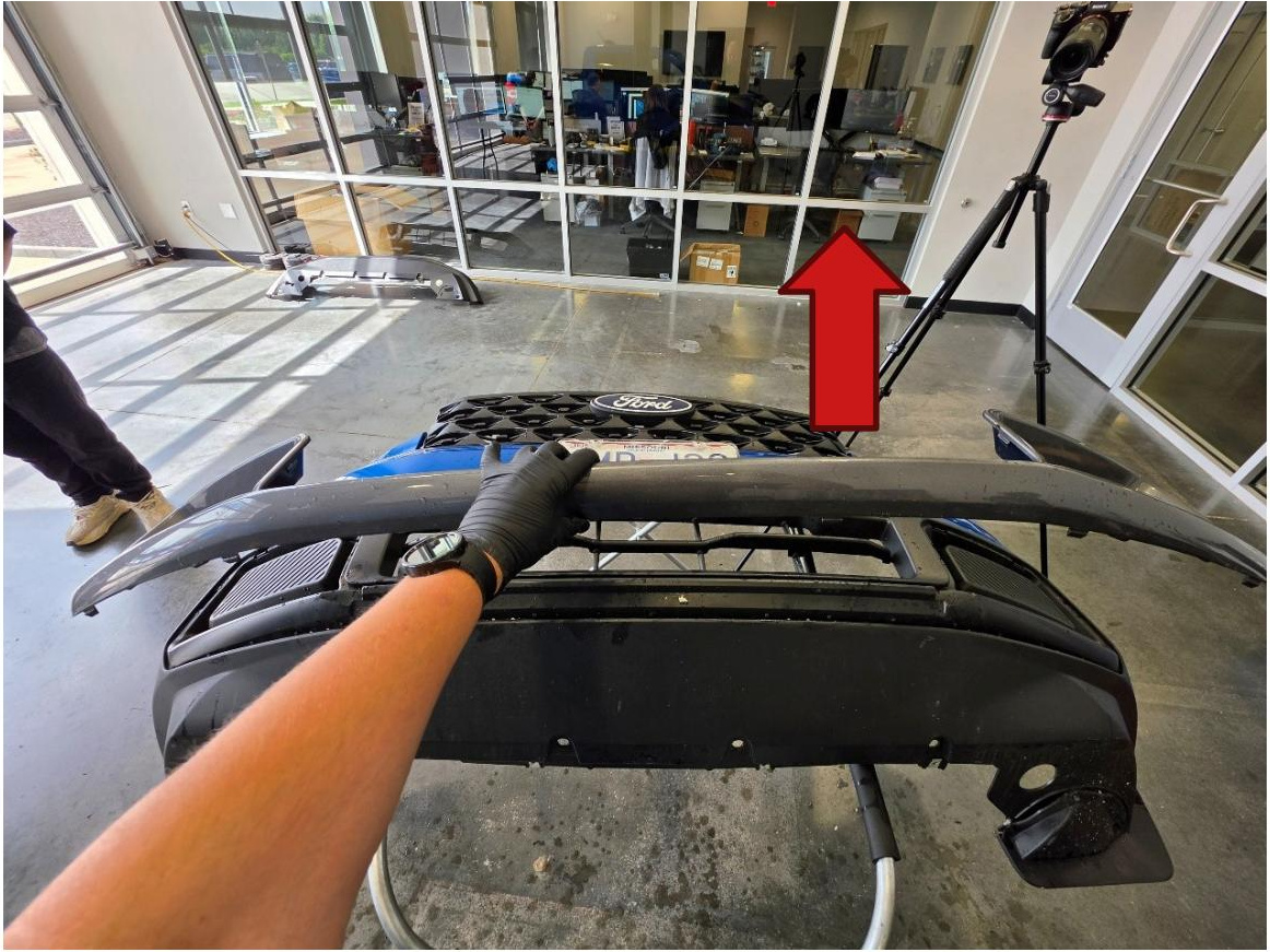
Step 14 — Trace the bumper cut lines
From the back of the bumper, place the left and right support rings into their corresponding fog-light pockets. Hold each ring fully in position and use a silver marker to trace along its lower edge, then remove the rings.
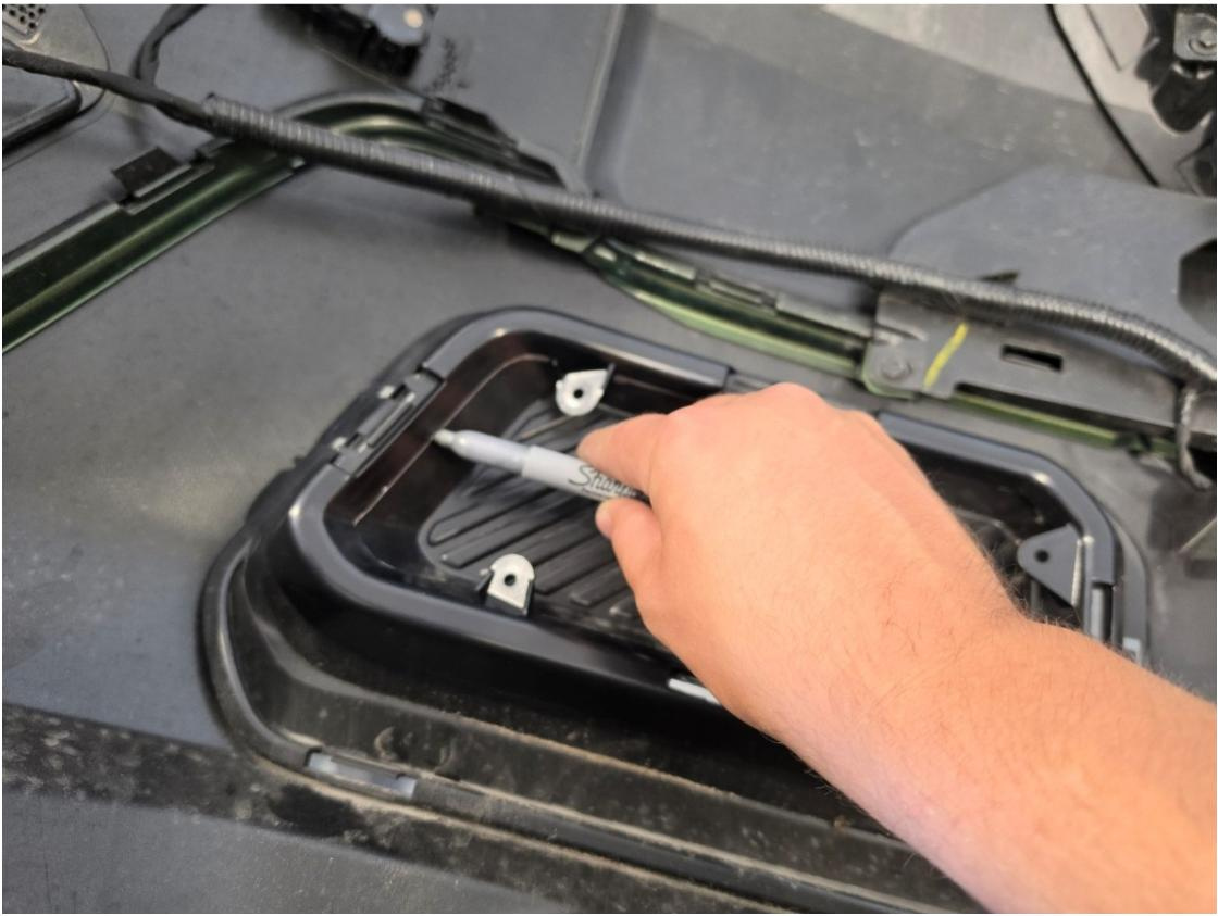
Step 15 — Cut the bumper pockets
Use a rotary tool with a cutting disc to carefully cut along each traced line. Make controlled passes and avoid cutting into the surrounding bumper plastic.
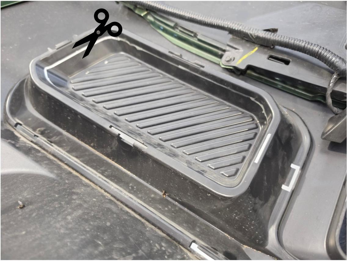
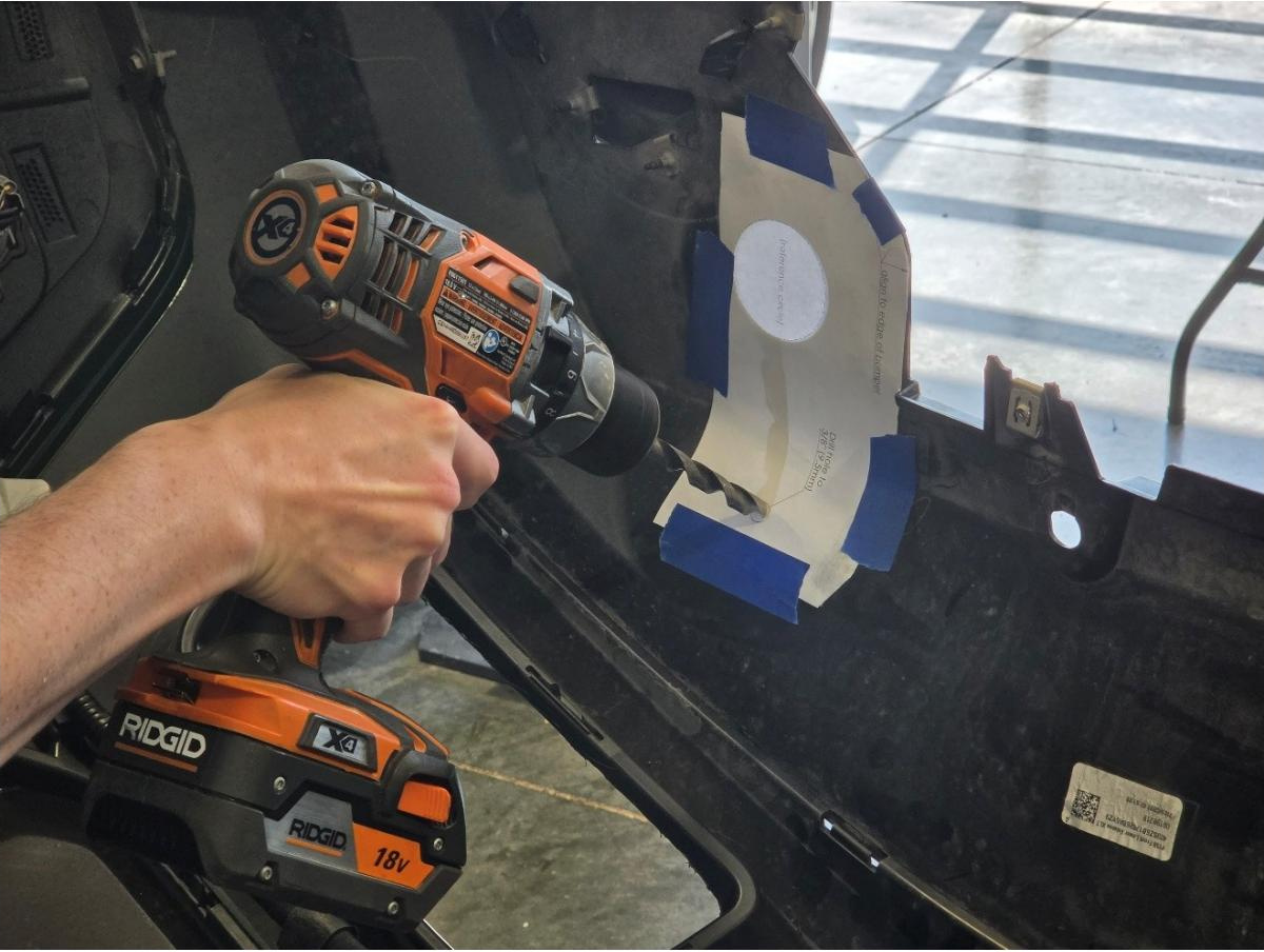
Step 16 — Drill the aiming access holes
Cut out the provided paper drill template and tape it to the inside of the bumper in the position shown. Drill a 3/8" access hole at the indicated location, then repeat this process on the opposite side.
Step 17 — Reinstall the aesthetic surround
Turn the bumper front-side up. Align the aesthetic surround with the bumper and press each retaining clip back into place until the surround is fully seated.
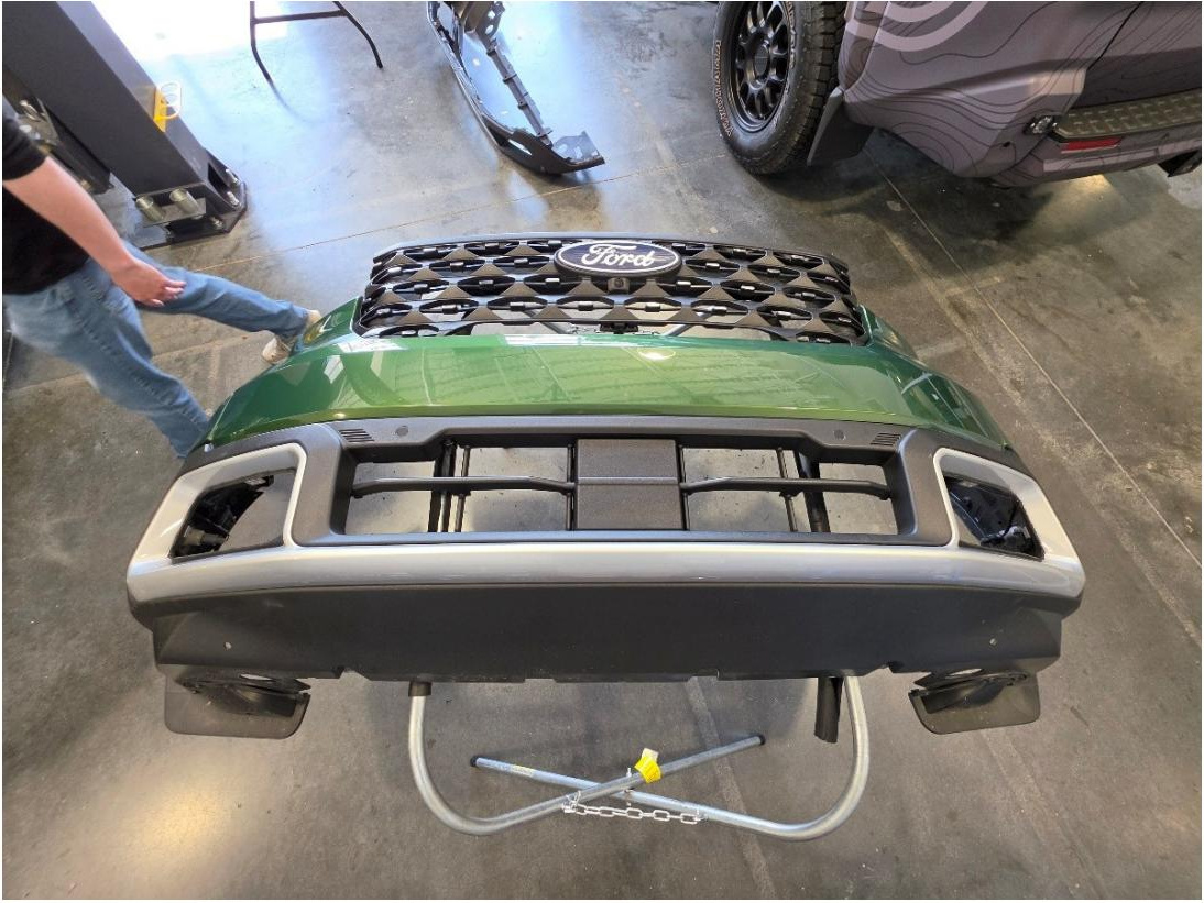
Step 18 — Install the lamps into the bezels
Match each fog lamp with its corresponding left- or right-side bezel, then press the lamp into the bezel until all retaining tabs snap securely into place.
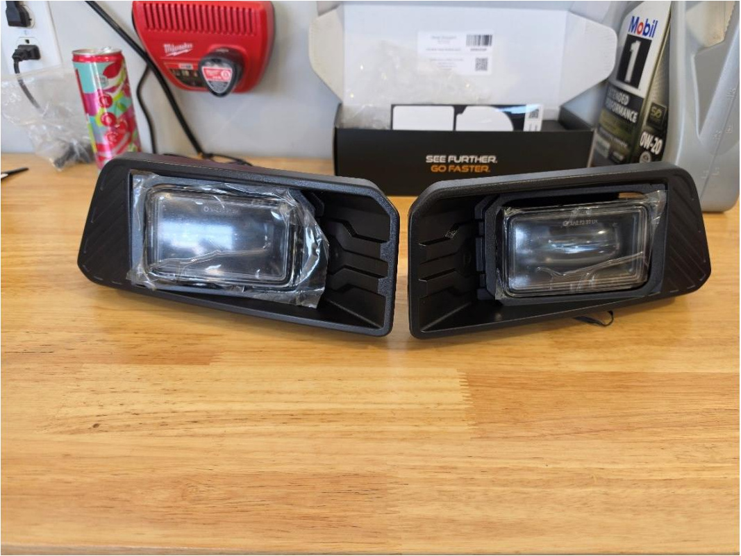
Step 19 — Assemble the aiming hardware
On the back of each fog-light assembly, install the included spring, adjustment screw, square nut, and centering cone in the order shown.
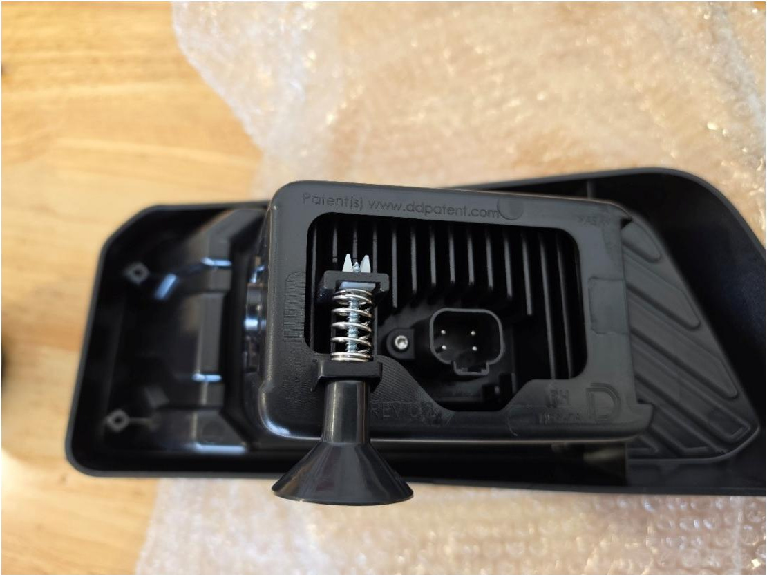
Step 20 — Mount the fog-light assemblies
Hold the bezel against the front of the bumper and the matching support ring against the back, sandwiching the bumper between them. Use a T15 Torx bit and the included screws and washers to secure the two pieces together. Tighten the hardware evenly without overtightening, then repeat this process on the opposite side.
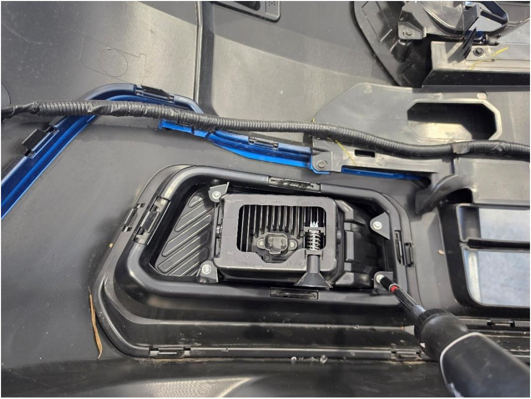
Step 21 — Connect the hybrid chassis ground
Hybrid models only: In front of the driver-side fuse box, use an 8mm socket to remove the chassis-ground fastener. Place the fog-light harness ground terminal over the mounting point, then reinstall and tighten the fastener.
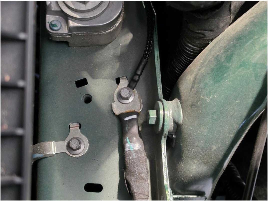
Step 22 — Connect harness power and ground
Make sure the ignition and all exterior lighting are switched off before making the power connections.
Hybrid models: Use a 13mm socket to attach the positive lead of the fog-light harness to the distribution bus on the left side of the fuse panel. Reinstall and tighten the factory fastener.
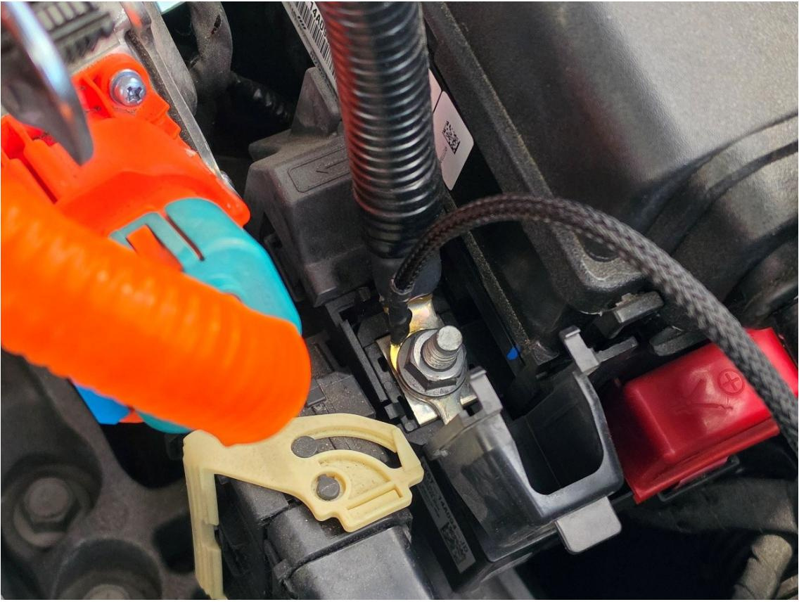
Non-hybrid models: Attach the positive and ground leads of the fog-light harness to the corresponding battery terminals, then tighten both connections securely.
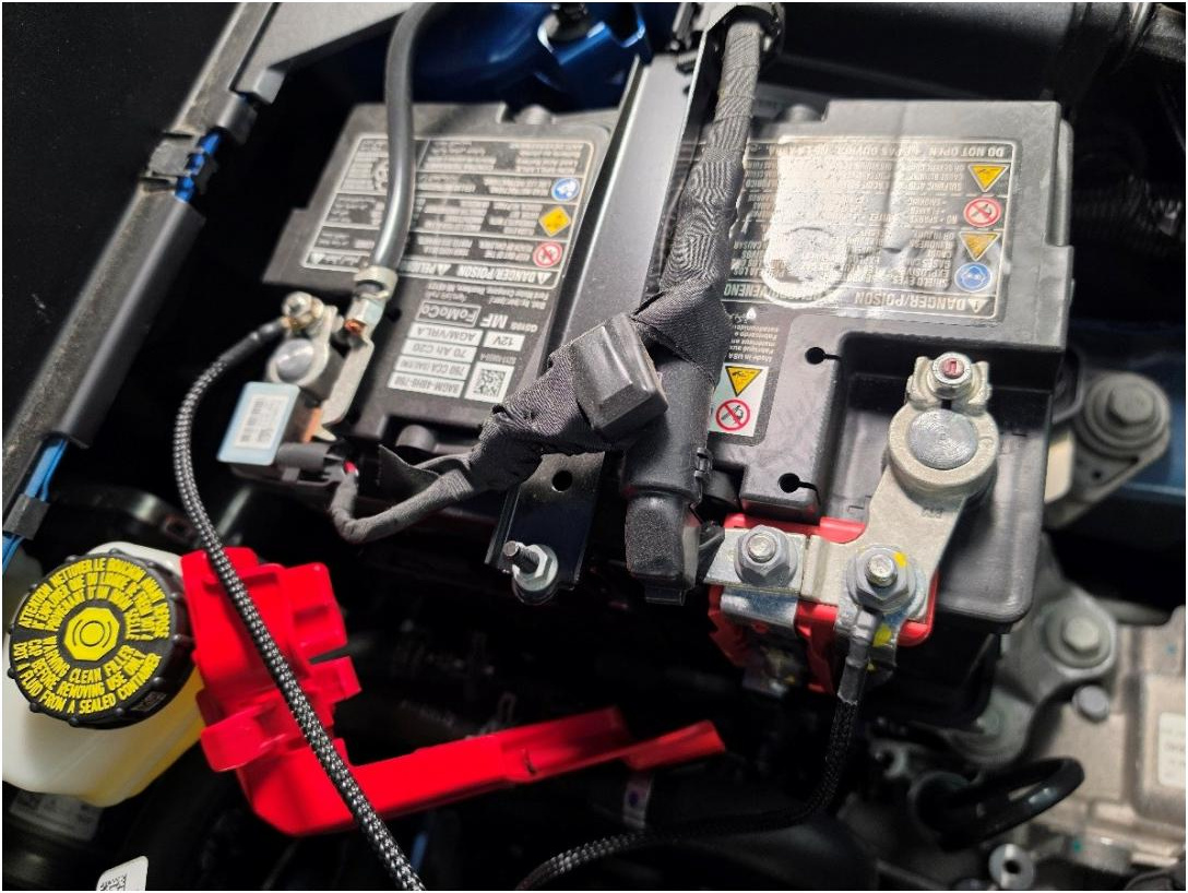
Step 23 — Disconnect the driver-side headlamp connector
Behind the driver-side headlamp, locate the factory inline connector coming from the rear of the headlamp. Depress the locking tab and disconnect it.
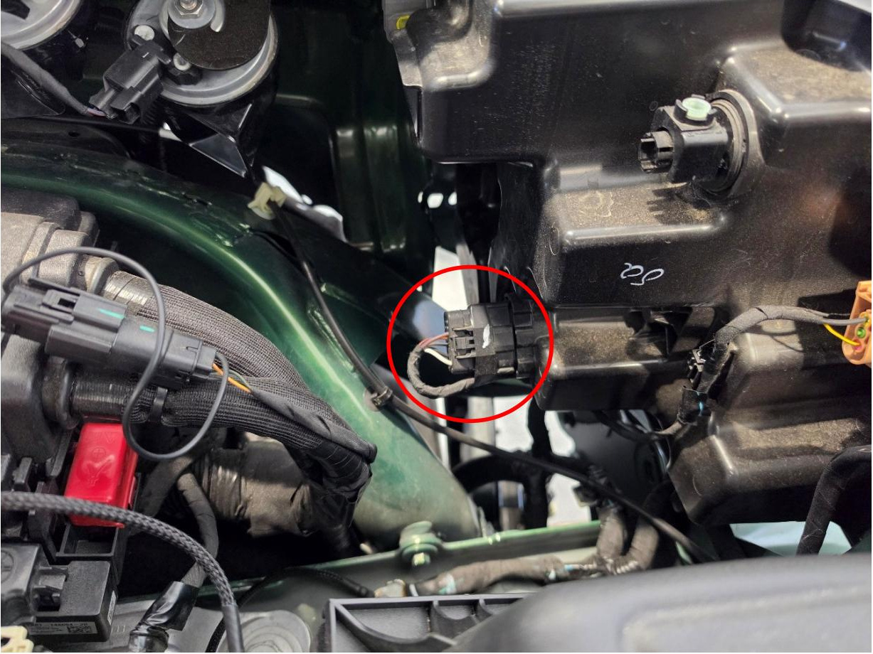
Step 24 — Install the inline headlamp connection
Plug the matching inline section of the fog-light harness between the driver-side headlamp and the factory connector. Confirm that both connections click fully into place.
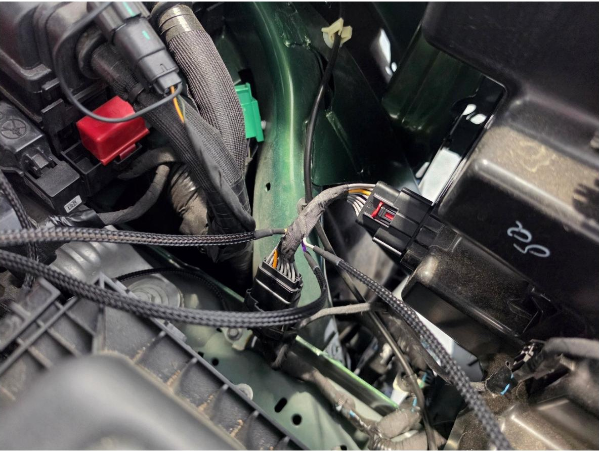
Step 25 — Select the headlamp trigger lead
Determine whether the vehicle is equipped with projector- or reflector-style factory headlamps. Connect the single-pin trigger connector to the matching labeled lead on the fog-light harness. Cap and coil the unused lead so it remains protected and out of the way.
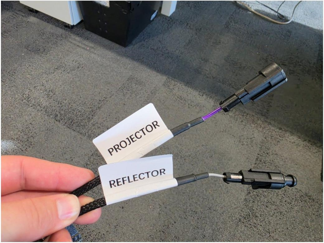
Step 26 — Route the driver-side harness and secure the relay
Feed both fog-lamp connectors and the 2-pin sidemarker inline connector down into the driver-side fog-light pocket. Use a zip tie to secure the relay to the factory wiring bundle entering the fuse box, keeping the harness away from hot or moving components.
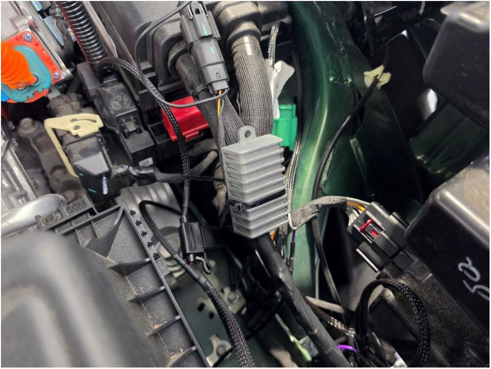
Step 27 — Route the passenger-side lamp connector
Route the longer fog-lamp connector across the top of the lower radiator shroud and into the passenger-side fog-light pocket. Follow the factory wiring path and secure the harness as needed.
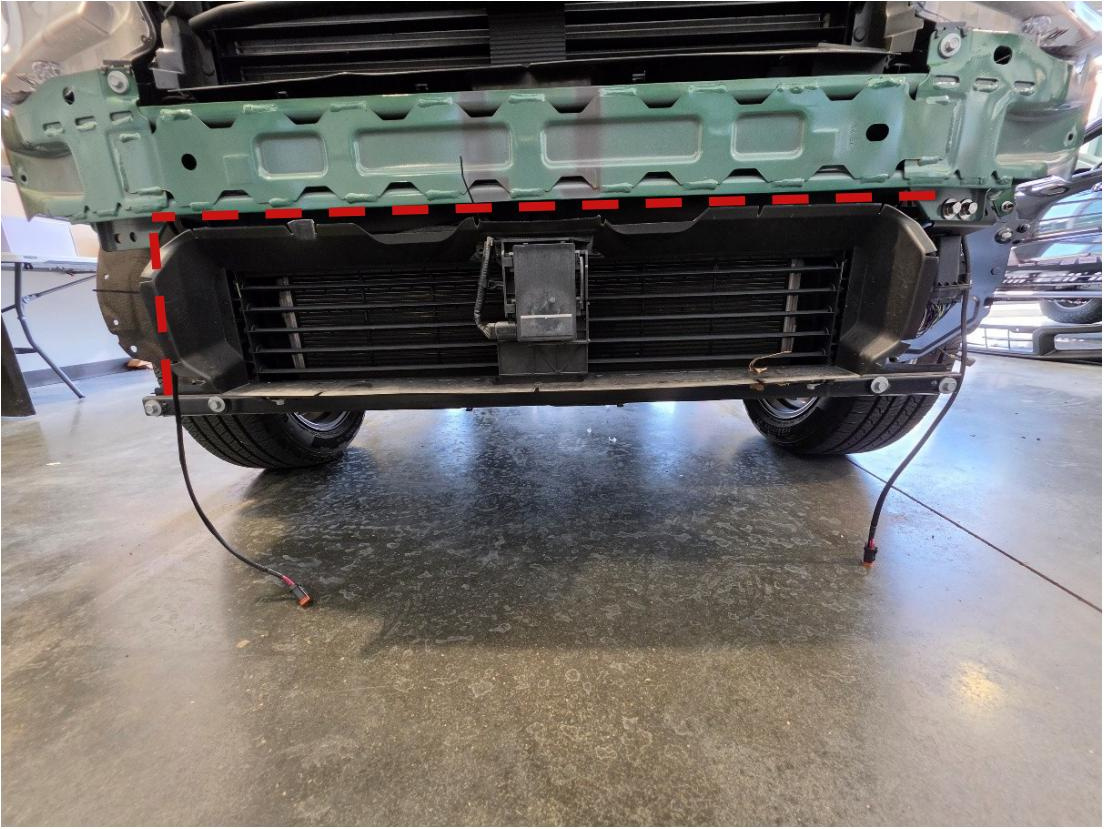
Step 28 — Connect the sidemarker inline harness
Place the bumper upright on a soft surface directly in front of the vehicle. At the driver-side sidemarker, disconnect the factory 2-pin connector and install the matching inline section of the fog-light harness between the factory connector and the light.
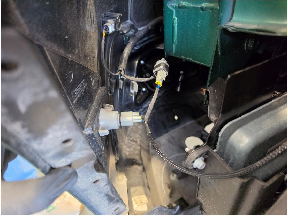
Step 29 — Connect the fog lamps
Connect the driver- and passenger-side lamp connectors to the rear of the fog lamps. Press each connector into place until its locking tab is fully seated.
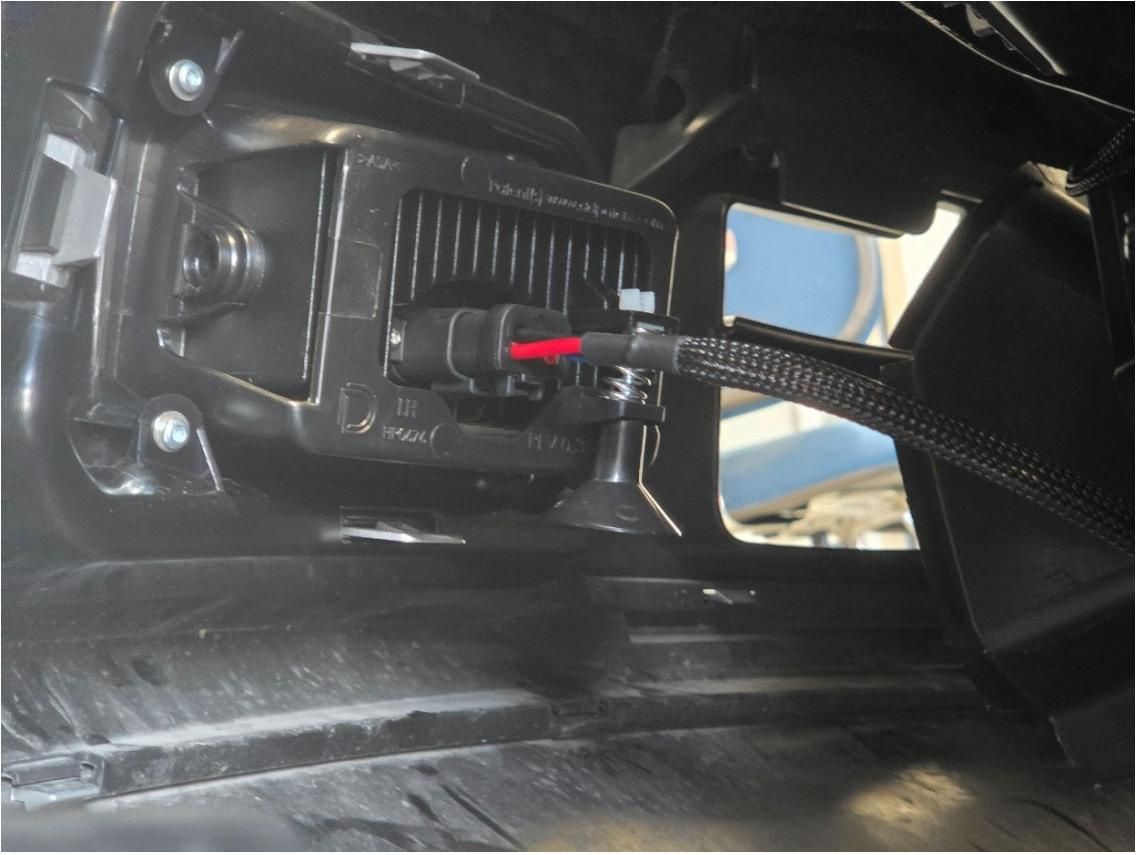
Step 30 — Reinstall the front bumper
Lift the bumper back onto the vehicle and engage the upper tabs and side corners. Reconnect the factory bumper harness, then reinstall the bolts, screws, and push pins removed earlier in reverse order.
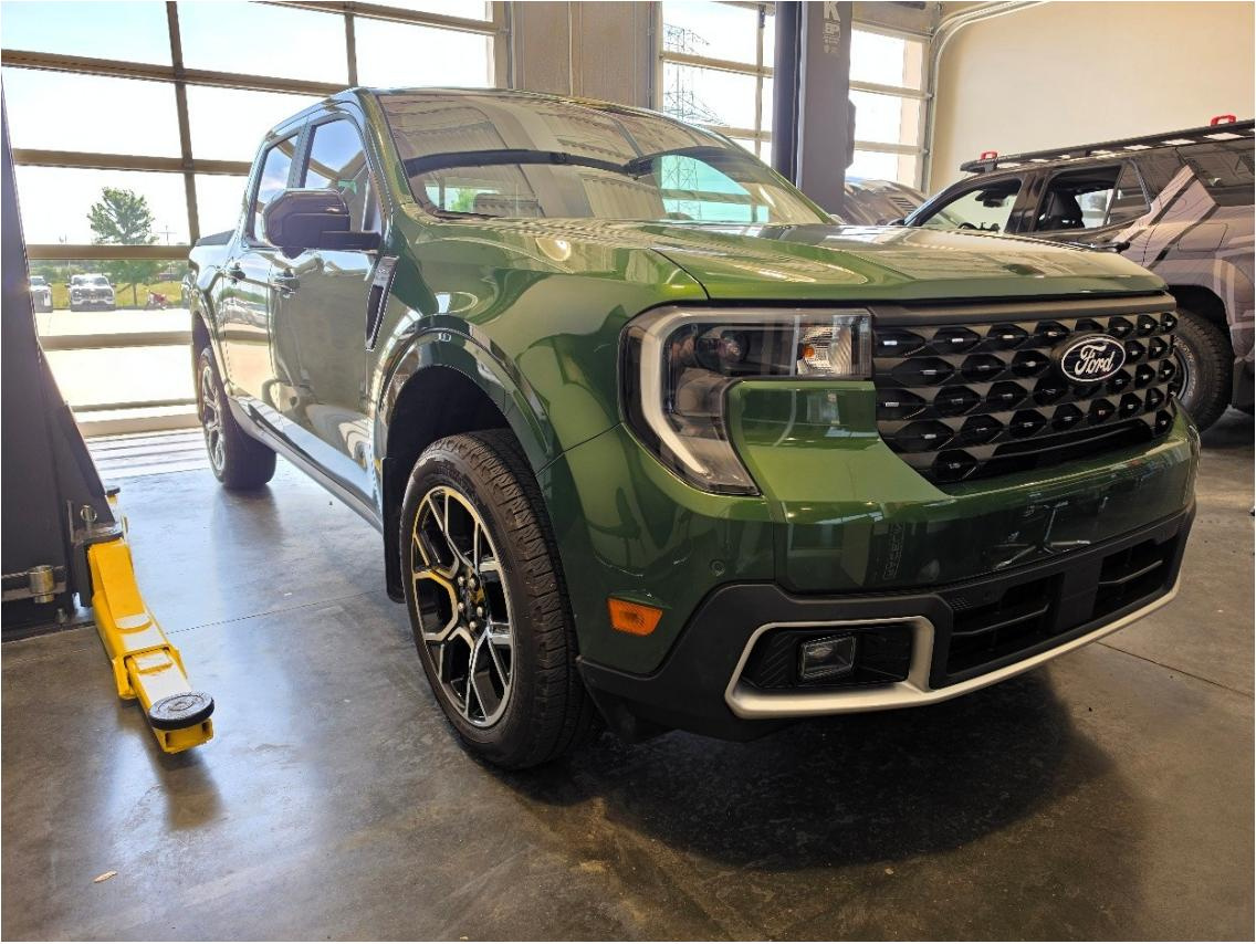
Step 31 — Aim the fog lamps
Insert a long Phillips screwdriver through the access hole drilled in Step 16 and engage the adjustment screw on the back of the fog lamp.
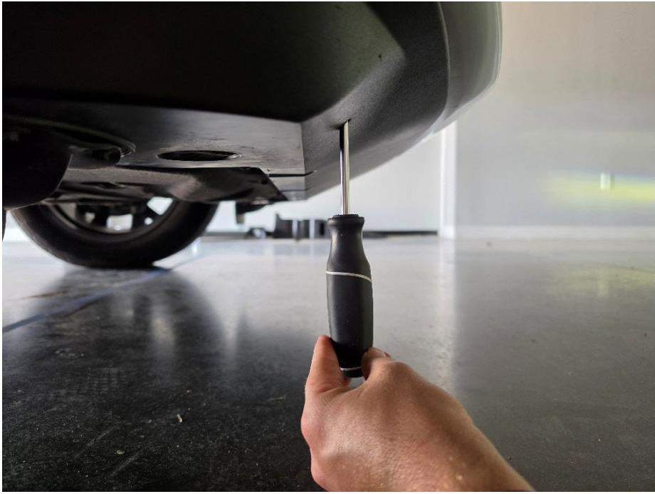
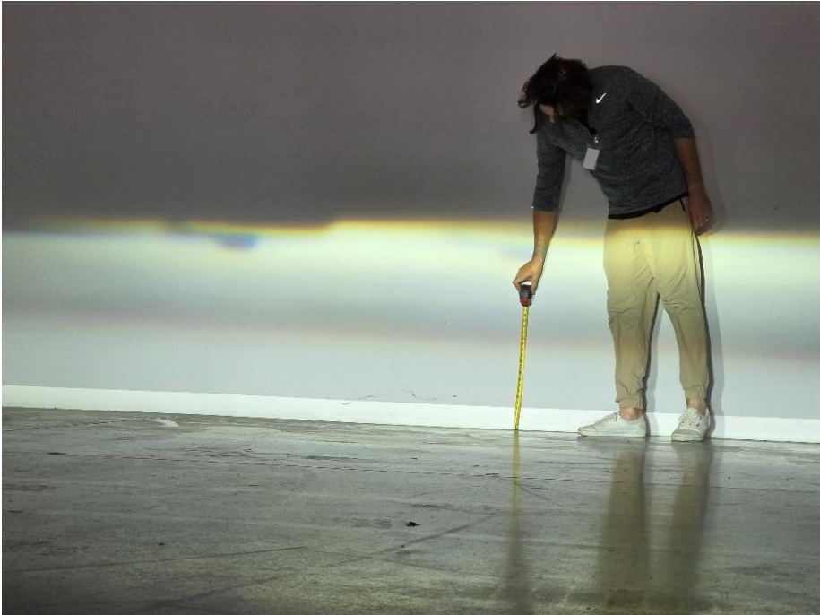
Rotate the screwdriver clockwise to raise the beam or counterclockwise to lower it. Adjust both lamps to a 0-2 degree downward angle.

Step 32 — Test operation and verify aim
Test all lighting functions. The amber backlights should turn on with the parking lights, the main fog beams should turn on with the low beams, and the main fog beams should turn off when the high beams are activated.
On a level surface, check the beam pattern against a wall to confirm that both lamps are even and aimed slightly downward. Repeat Step 31 if further adjustment is needed.
The installation is now complete. Enjoy your new Elite Series Add-On Fog Lamp Kit for the 2025-2027 Ford Maverick!
Questions About the Installation?
If you have any questions about installing the Elite Series Add-On Fog Lamp Kit for the 2025-2027 Ford Maverick, contact us via our support page.
Where Can I Buy the Elite Series Add-On Fog Lamp Kit for the 2025-2027 Ford Maverick?
If you're ready to upgrade your 2025-2027 Ford Maverick with the Elite Series Add-On Fog Lamp Kit, visit DiodeDynamics.com or use our Dealer Locator to find a dealer near you.
Want to know more about Diode Dynamics products? Visit DiodeDynamics.com and subscribe to our newsletter for new product releases and more!
This Installation Guide is for the following SKU: DD8913, DD8914

Share This Post