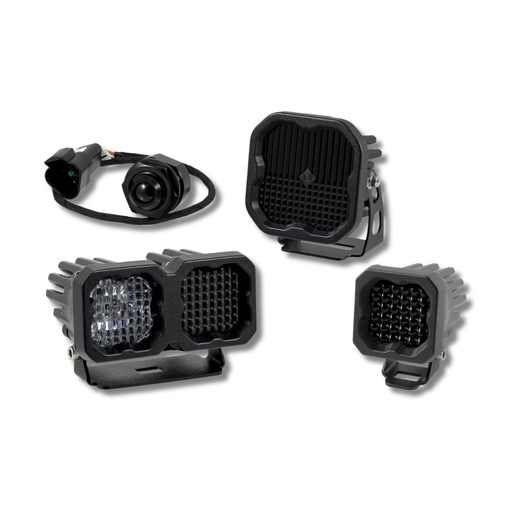



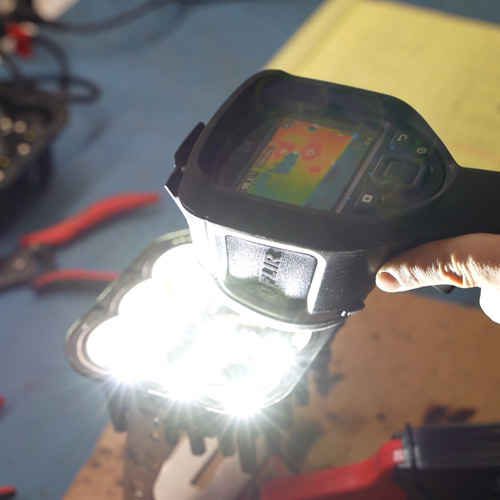
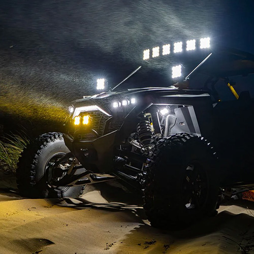
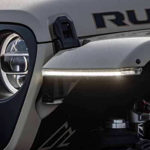

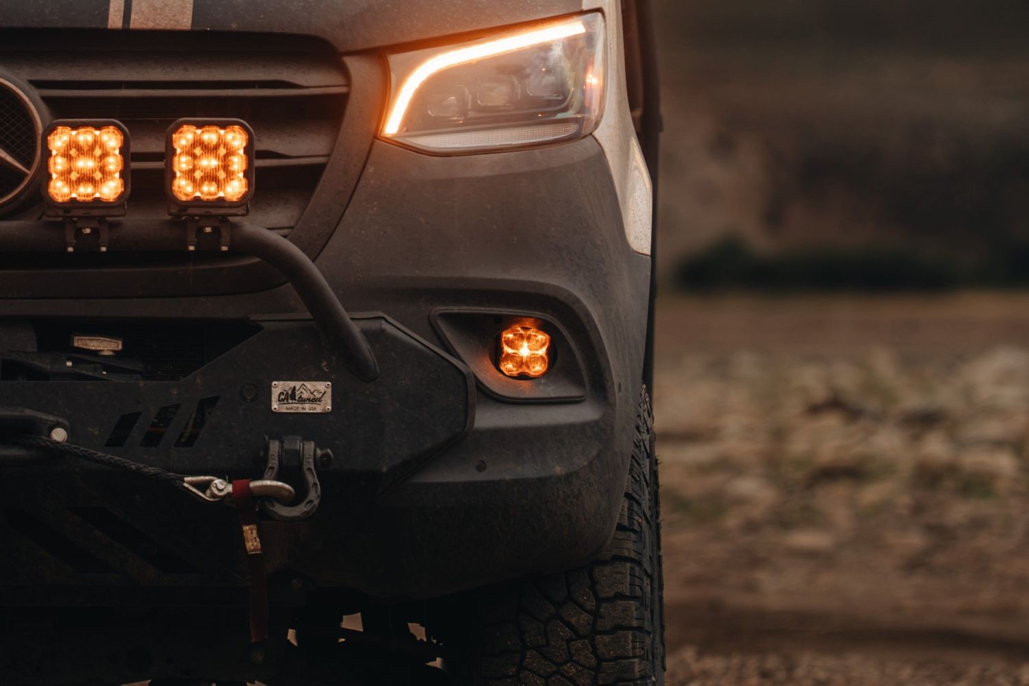
The SS3 LED Fog Light Kit for the 2019-2026 Mercedes-Benz Sprinter replaces the factory fog lights with powerful, road-legal output and distinctive backlighting. This installation guide will provide you with detailed instructions on how to install the SS3 LED Fog Light Kit for the 2019-2026 Mercedes-Benz Sprinter. Continue reading for step-by-step instructions below!
Table of Contents
- Installation Tools
- Installation Instructions
- SmartSelect Programming
- Questions About the Installation?
- Where Can I Buy the SS3 LED Fog Light Kit for the 2019-2026 Mercedes-Benz Sprinter?
Installation Tools
- Trim removal tool
- T20 Torx driver
- T25 Torx driver
- T30 Torx driver
- 17mm wrench
- 4mm Allen wrench
- 10mm socket and ratchet
Installation Instructions
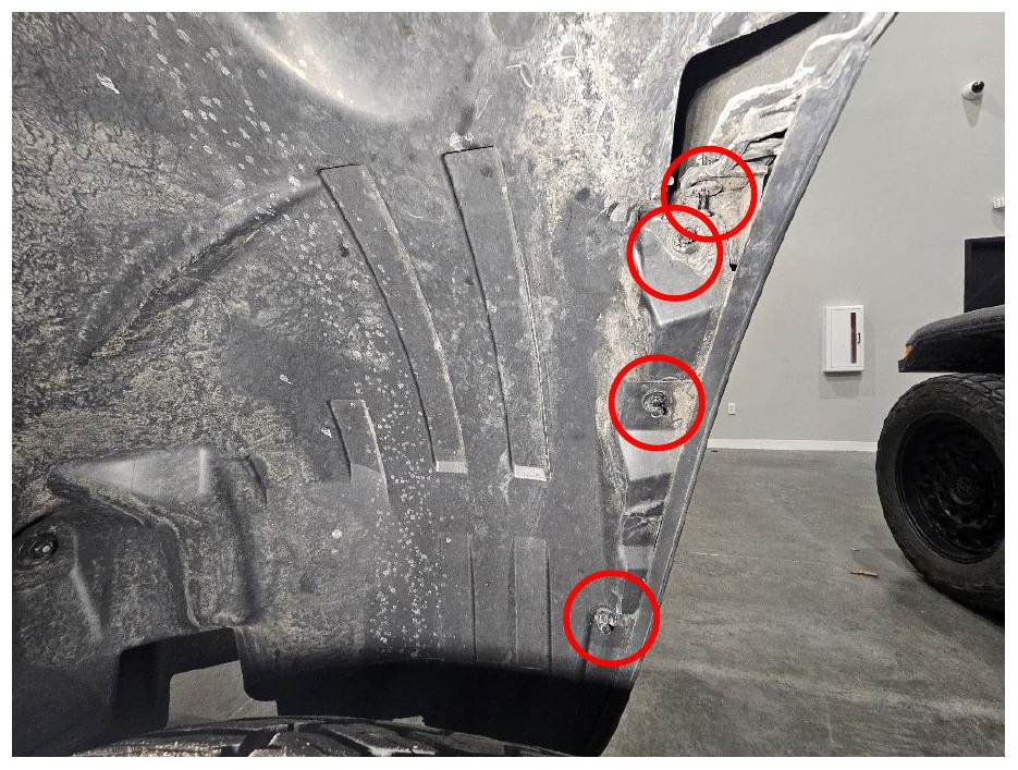
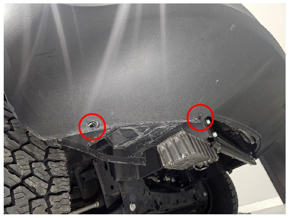
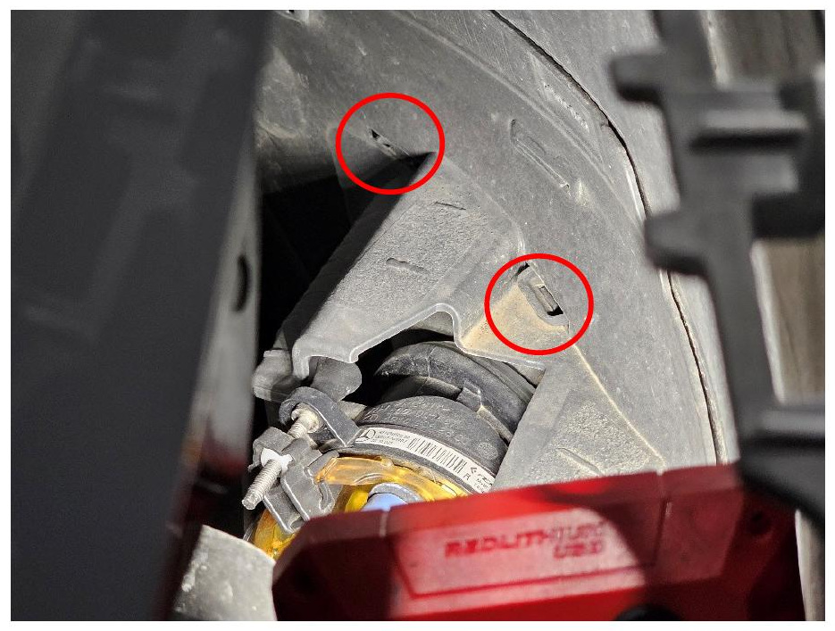
Step 1 — Remove the fender liner clips
Use a trim removal tool to remove the six push-pin clips securing the fender liner. Repeat this process on the other side of the vehicle.
For faster access, experienced installers may proceed directly to Step 4. However, completing Steps 1 through 3 provides additional working clearance and reduces the risk of damaging the bumper or surrounding trim.
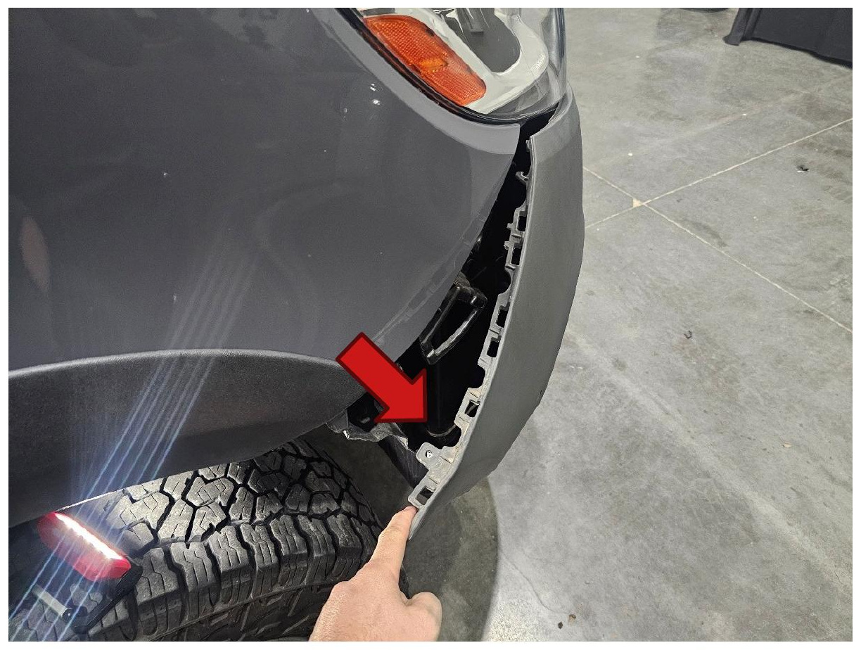
Step 2 — Separate the bumper from the quarter panel
Carefully pull the bumper away from the quarter panel to release the retaining clips. Repeat this process on the other side of the vehicle.
Step 3 — Release the fog light bezel tabs
Reach behind the factory fog light and apply outward pressure to the four mounting tabs. While holding the tabs, pull the fog light bezel outward from the front of the vehicle to release it.
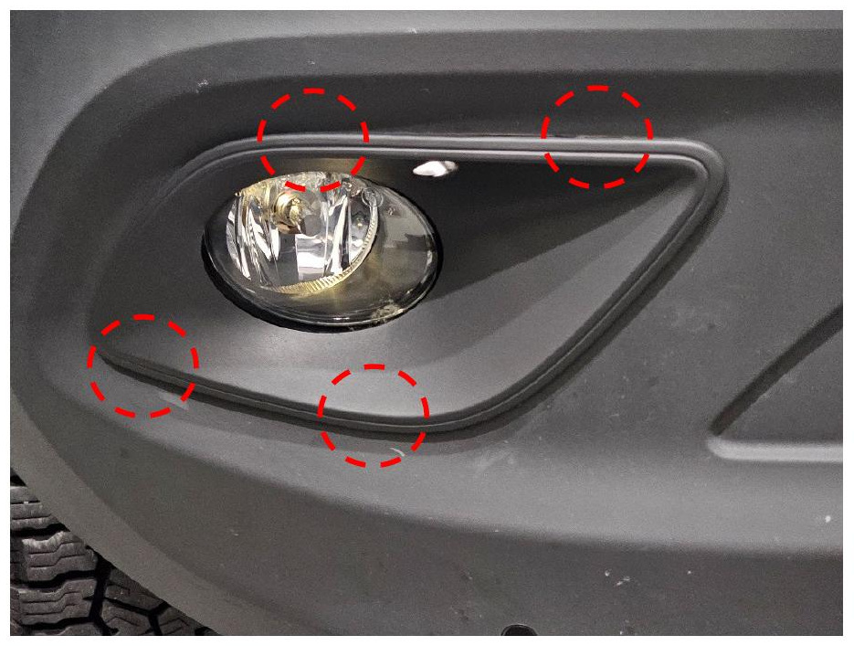
Step 4 — Remove the fog light bezel
Pull the fog light bezel away from the vehicle and remove it. Repeat this process on the other side.
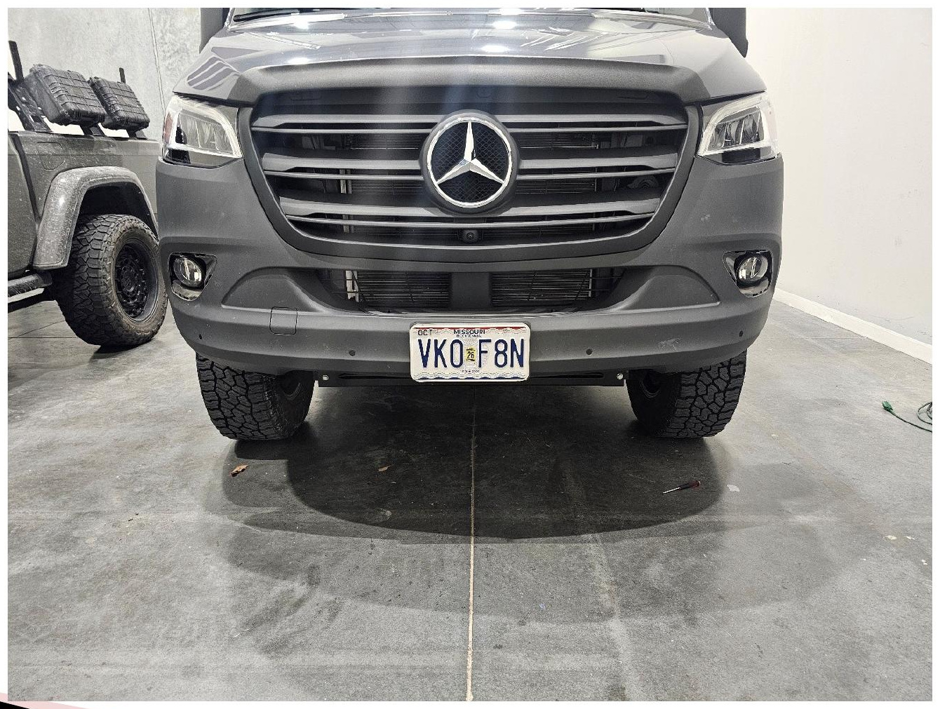
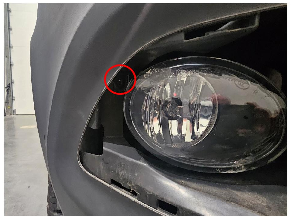
Step 5 — Remove the factory fog light
Use a T20 Torx driver to remove the screw securing the factory fog light. Pull the fog light assembly out of the vehicle, then disconnect the factory H11 connector.
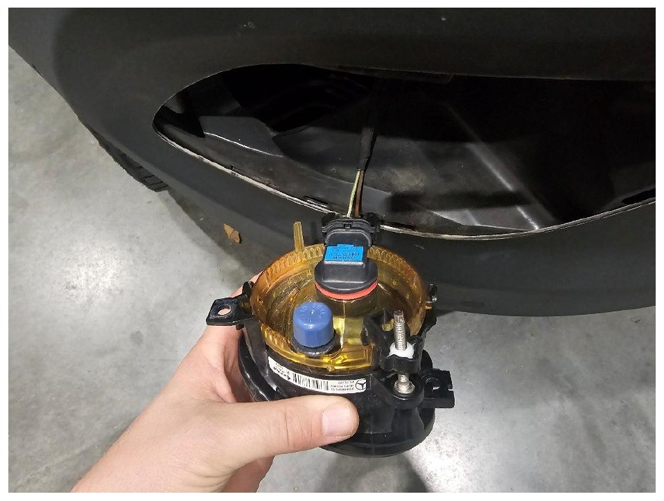
Step 6 — Assemble the SS3 fog lights
Use a 4mm Allen wrench and the included hardware to install each SS3 LED pod onto its corresponding mounting bracket.
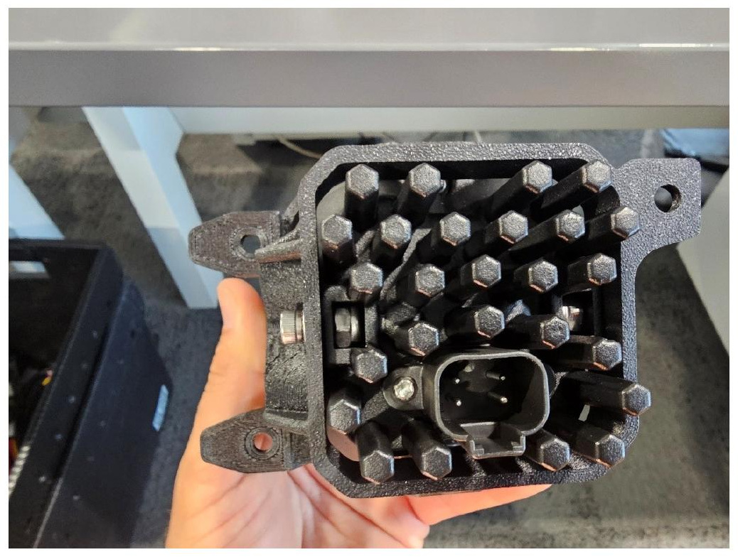
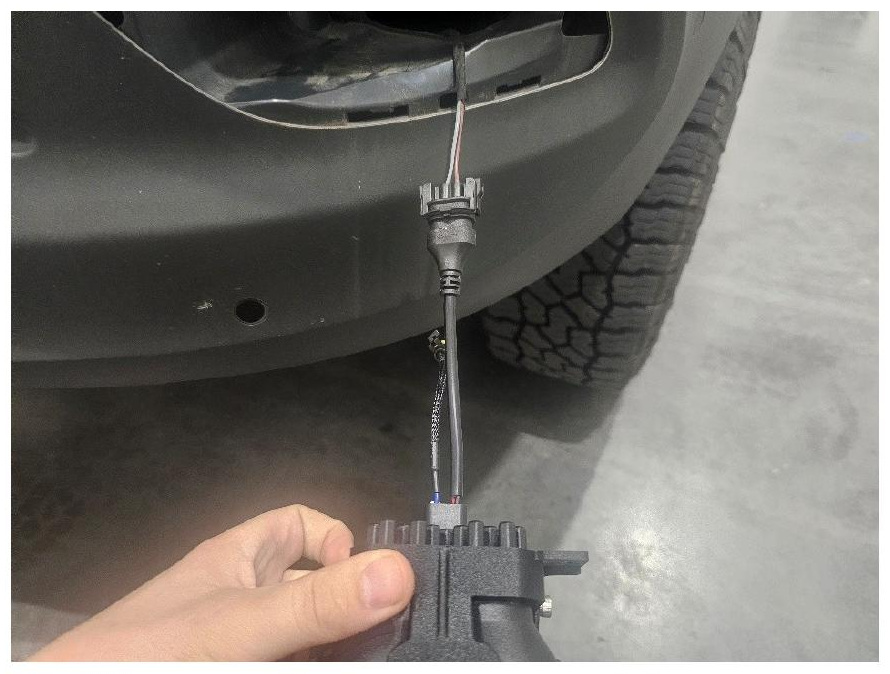
Step 7 — Connect the fog light adapter
Connect the included fog light adapter between the SS3 LED pod and the vehicle's factory fog light harness. The H11 connector is keyed and will only connect in the correct orientation.
IMPORTANT: Ensure the connector's locking latch passes completely over the small raised locking tab on the vehicle-side connector. If the latch has not cleared the tab, press down on the connector and push the two halves together until the latch snaps securely into place.
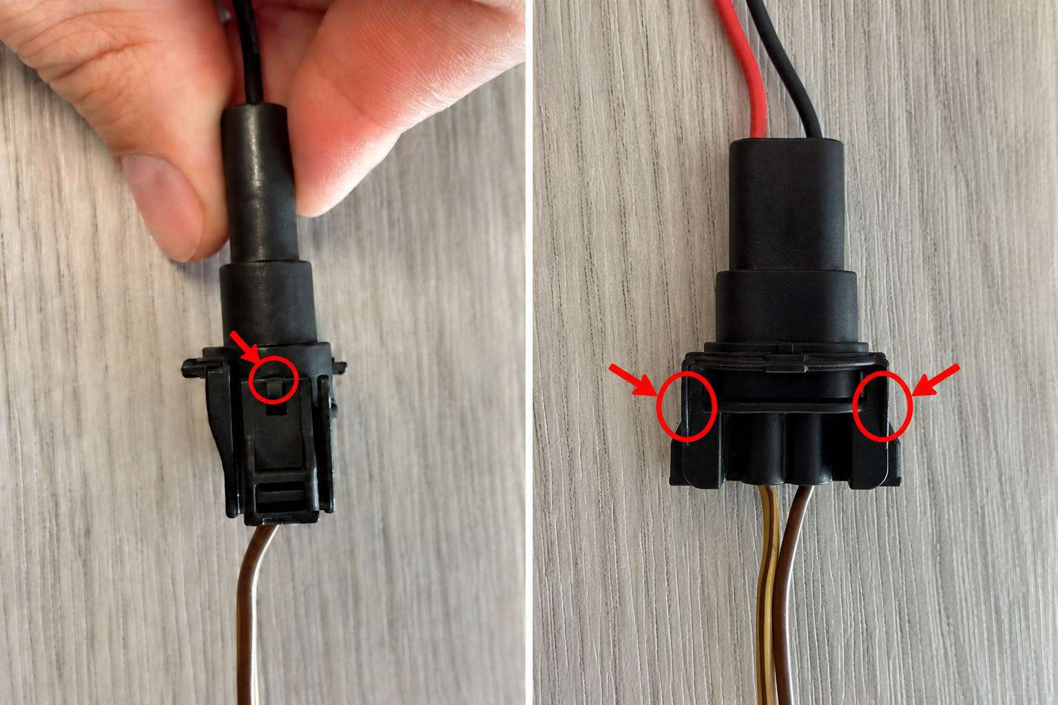
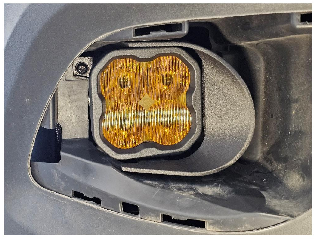
Step 8 — Install the SS3 fog light assembly
Position the SS3 fog light assembly in the factory mounting location. Reinstall the factory screw removed in Step 5 and tighten it using a T20 Torx driver. Repeat Steps 5 through 8 on the other side of the vehicle.
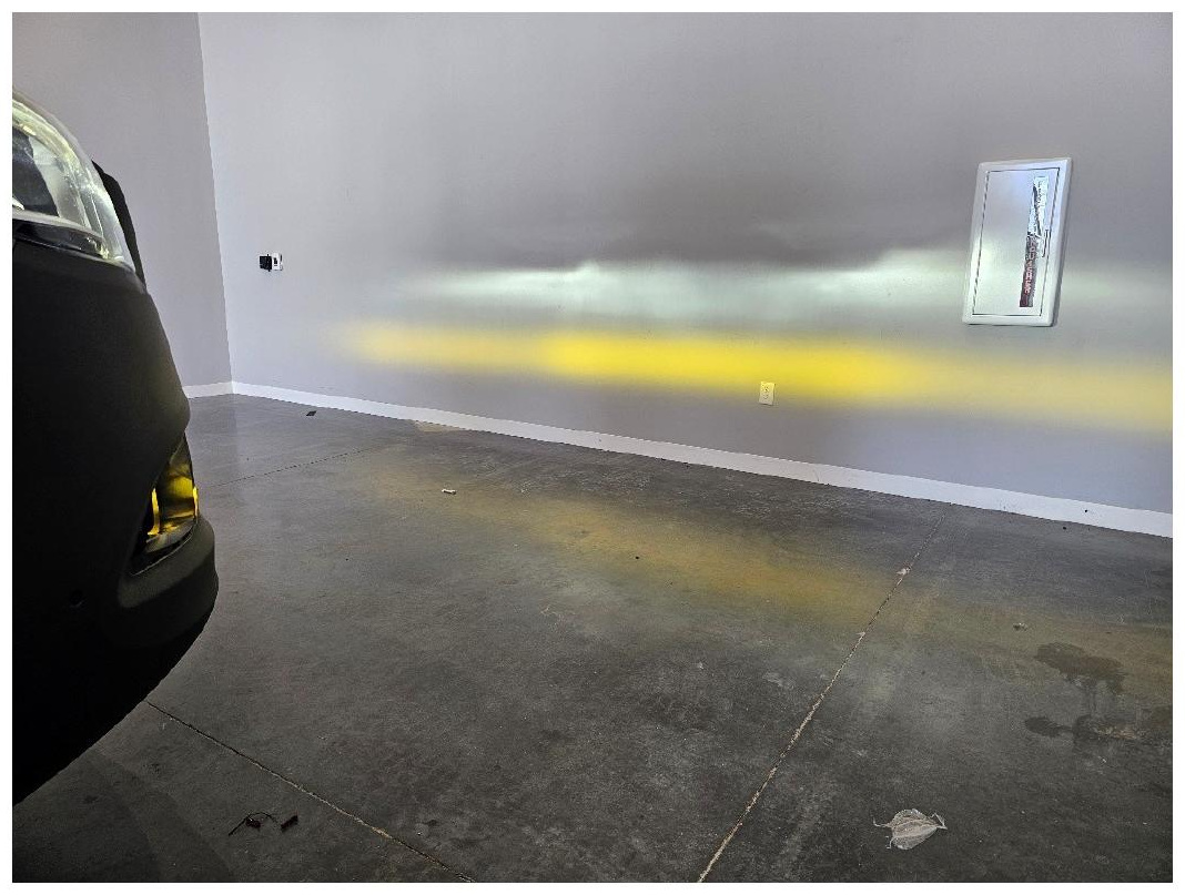
Step 9 — Aim the SS3 fog lights
Turn on the fog lights and adjust each SS3 LED pod up or down as needed. Aim both lights in accordance with applicable DOT standards, then tighten the mounting hardware to secure the adjustment.
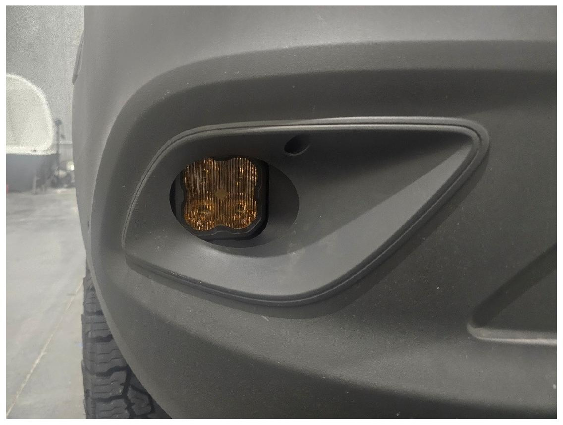
Step 10 — Reinstall the fog light bezels
Align each outer fog light bezel with the bumper and press it firmly into place until all retaining tabs engage.
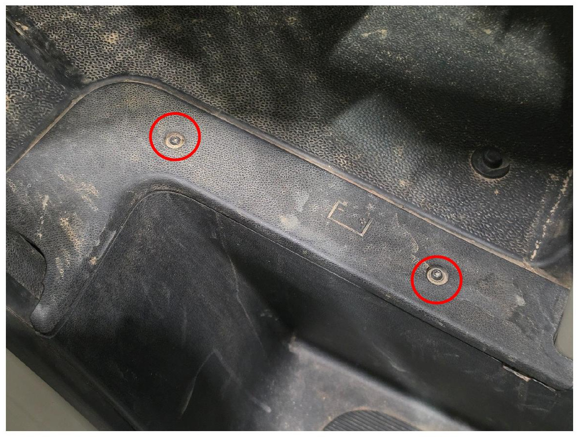
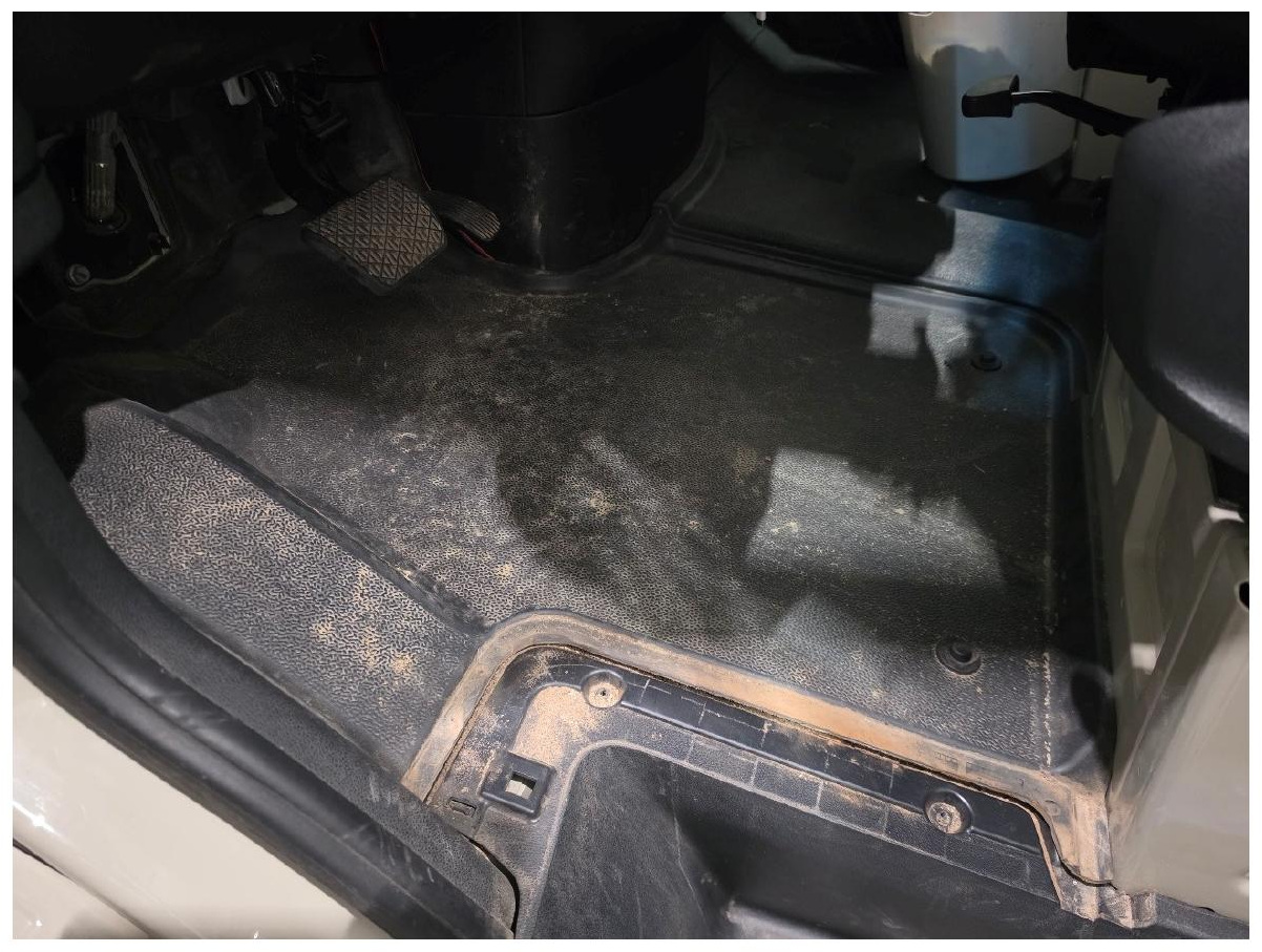
Step 11 — Remove the driver-side kick plate
To connect the SS3 backlighting, use a T25 Torx driver to remove the two screws securing the driver-side kick plate. Remove the kick plate from the vehicle.
Step 12 — Remove the floor insulation
Bend the floor insulation into a U-shape, move it away from the pedals, and remove it from the vehicle.
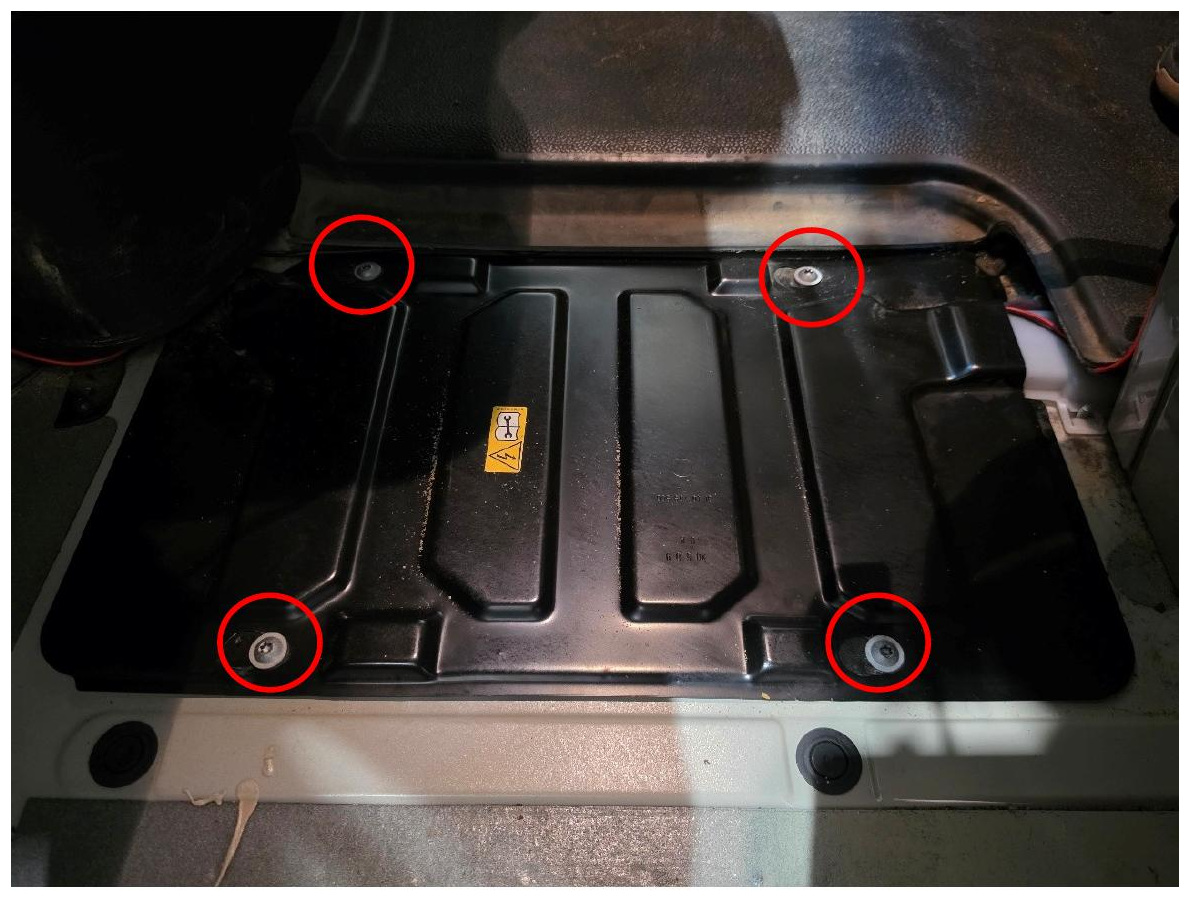
Step 13 — Remove the battery cover
Use a T30 Torx driver to remove the four screws securing the battery cover. Lift the cover away to access the battery.
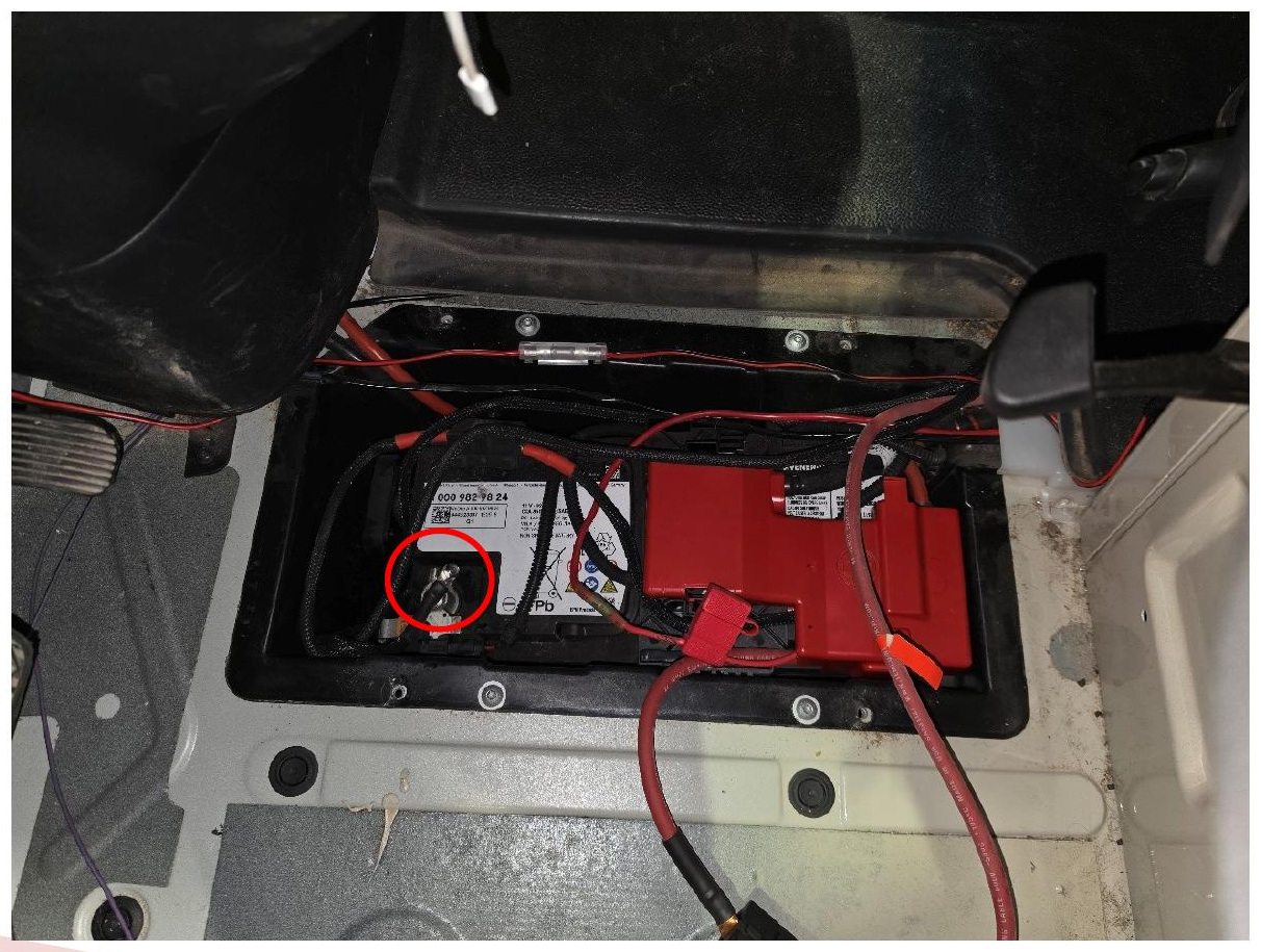
Step 14 — Disconnect the battery
Use a 10mm socket to disconnect the negative battery terminal.
IMPORTANT: The battery must remain disconnected before disconnecting the driver-seat connectors to avoid triggering an SRS airbag warning.
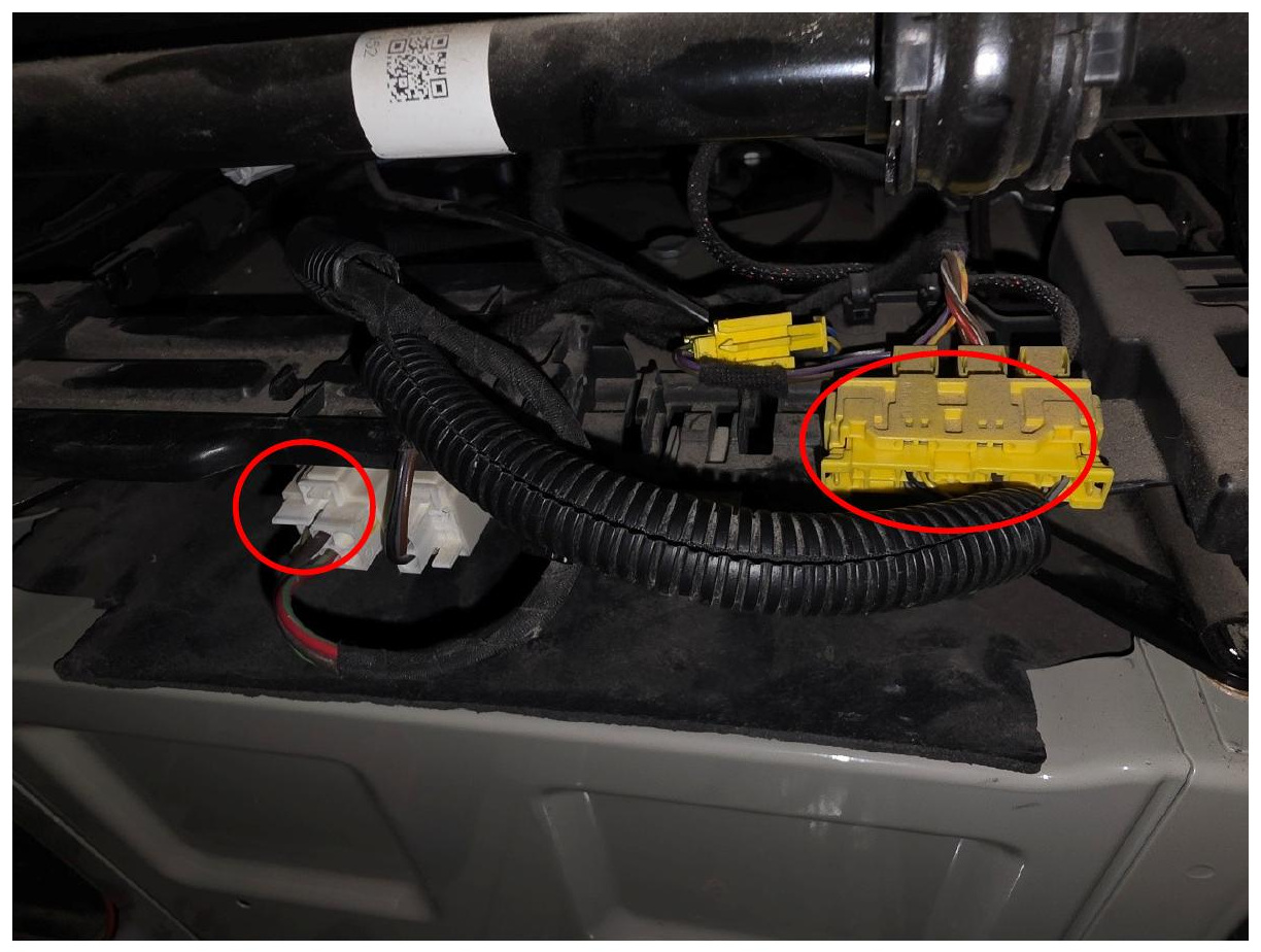
Step 15 — Disconnect the driver-seat connectors
With the negative battery terminal disconnected, unplug the two electrical connectors beneath the driver seat.
Step 16 — Remove the driver seat
Use a 17mm wrench to remove the four driver-seat pedestal fasteners, with one fastener located at each corner. Carefully remove the driver seat from the vehicle.
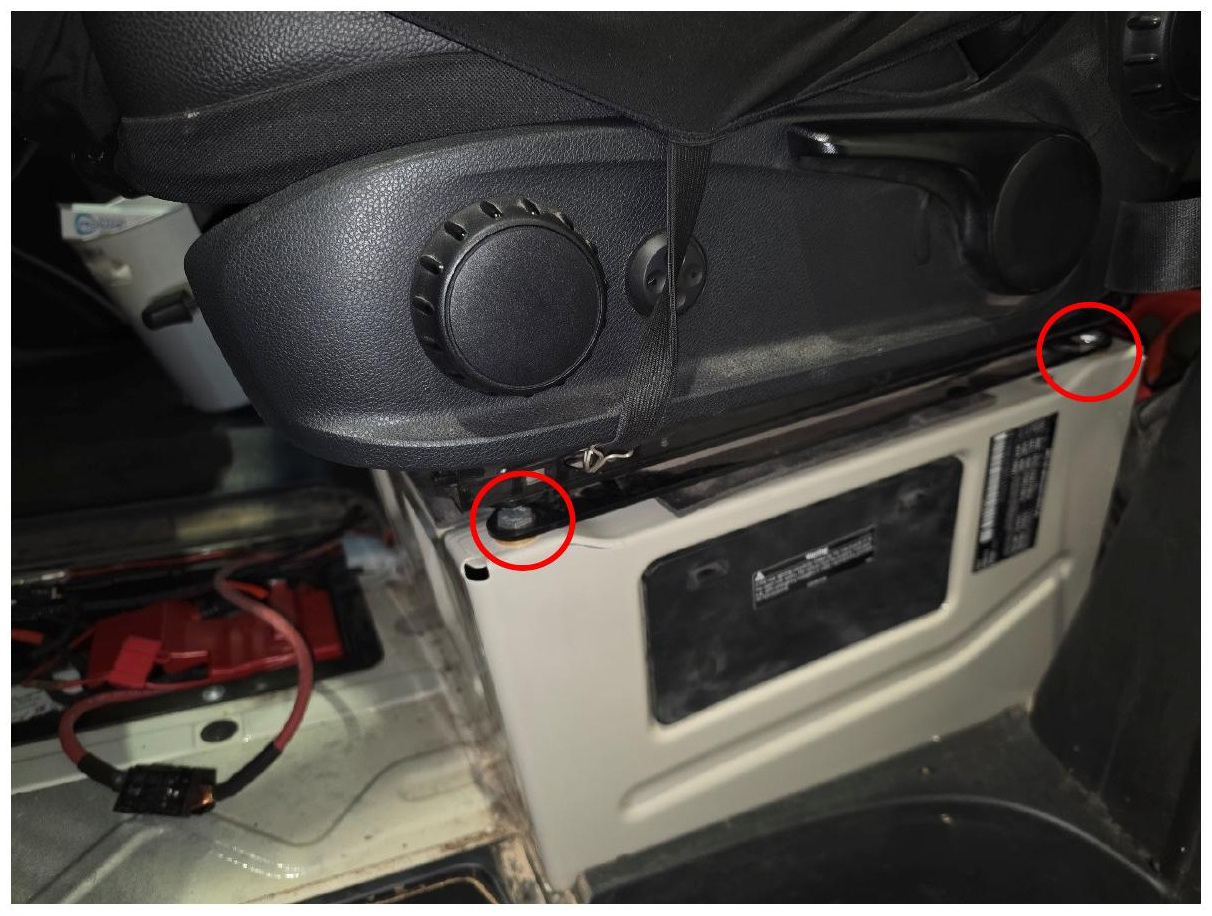
Step 17 — Remove the pedestal dust cover
Remove the dust cover to access the inside of the driver-seat pedestal.
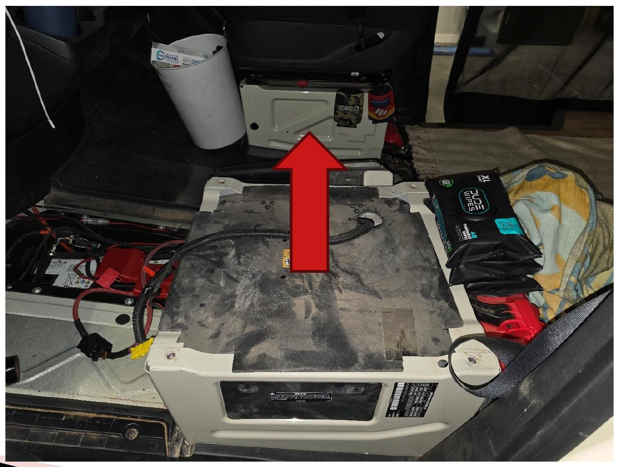
Step 18 — Move the BCM support assembly
Use a 10mm socket to remove the two nuts securing the BCM support assembly. Carefully move the assembly out of the way. The electrical connectors do not need to be disconnected.
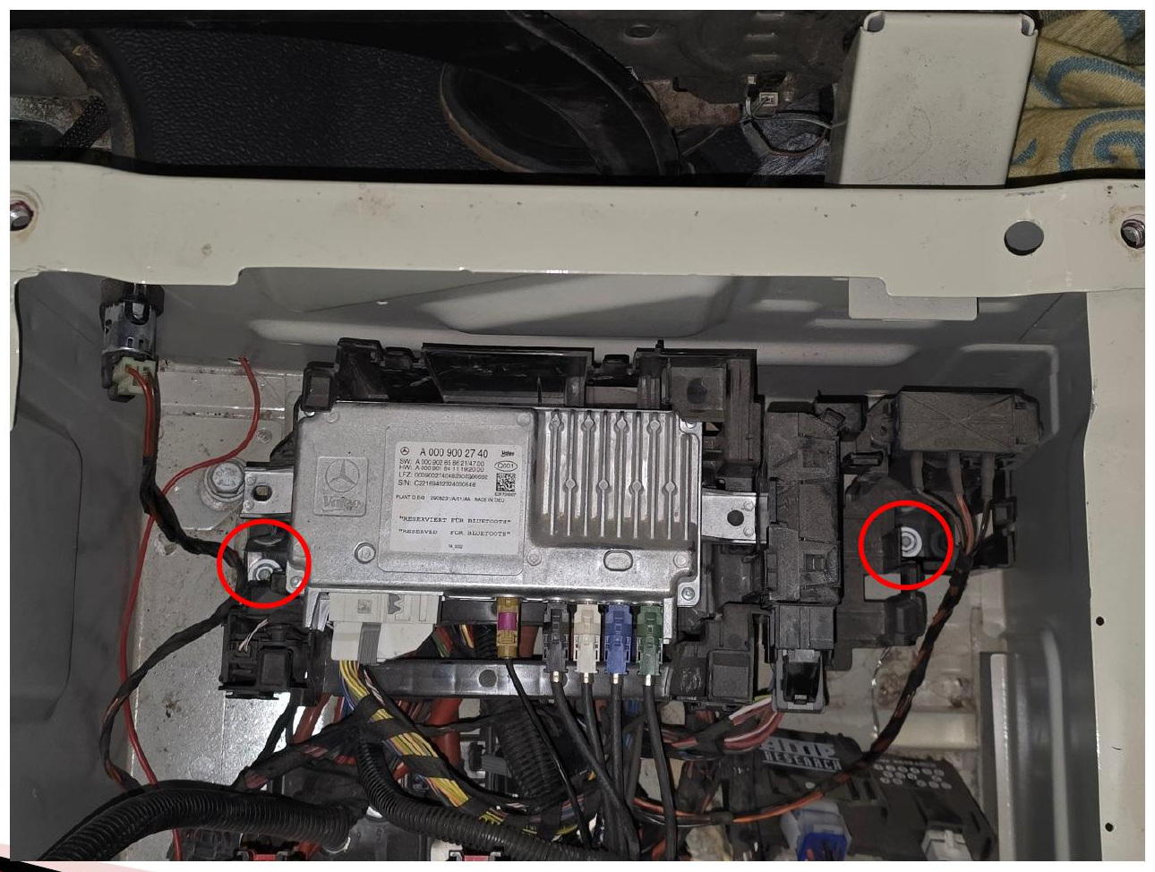
Step 19 — Feed the backlight harness through the wire tunnel
With the BCM support assembly moved aside, feed the quick-disconnect end of the included backlight harness through the factory wire tunnel and into the battery compartment.
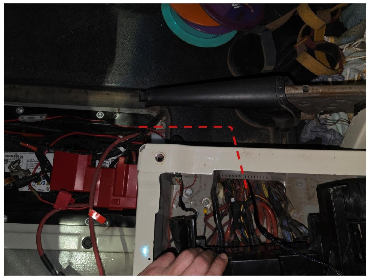
Step 20 — Route the harness to the firewall
From the battery compartment, route the backlight harness leads across the floor, through the driver-side kick-plate area, and toward the factory firewall access hole.
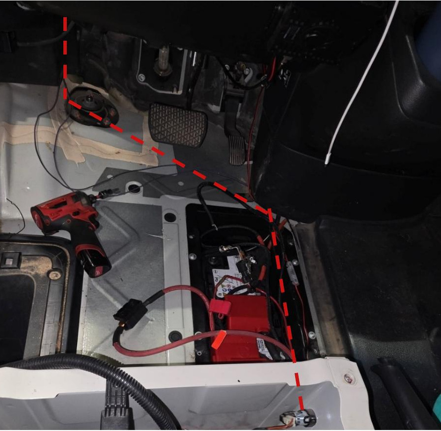
Step 21 — Route the connectors into the engine bay
Push both quick-disconnect connectors through the factory firewall access hole and into the engine bay.
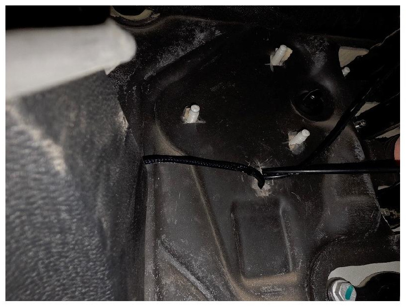
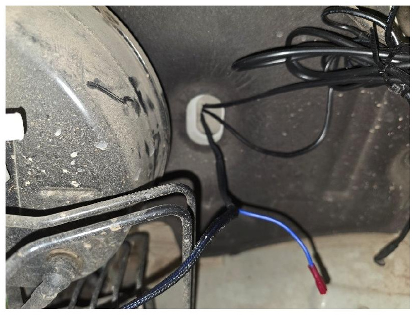
Step 22 — Connect the backlight harness
Route the longer end of the backlight harness across the engine bay to the passenger side. Route each fog light adapter upward from its SS3 LED pod, then connect the adapters to the corresponding ends of the backlight harness.
Secure the wiring away from hot, sharp, or moving components.
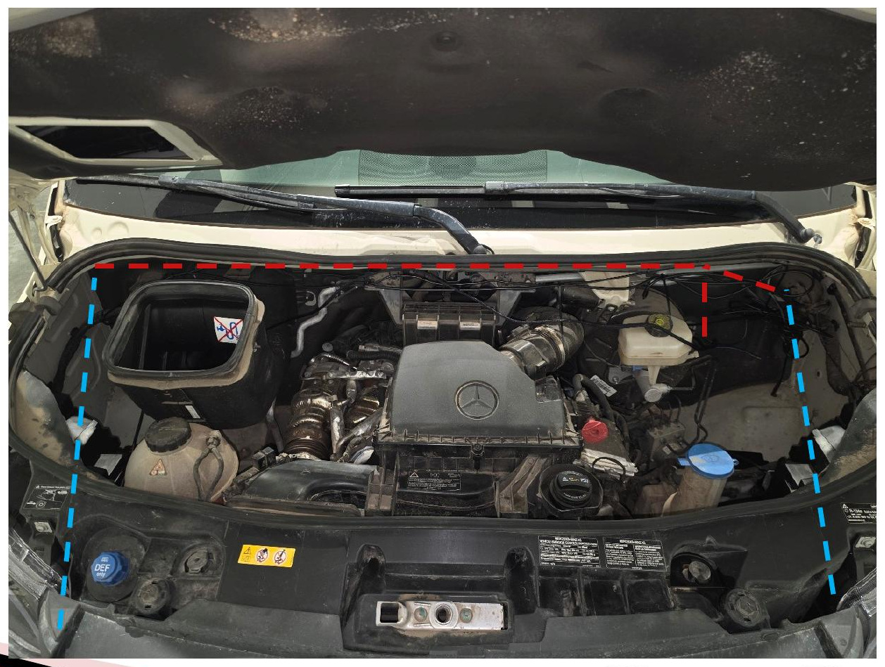
Step 23 — Prepare the add-a-fuse
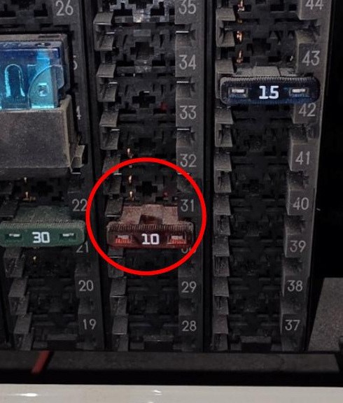
Open the fuse access panel on the side of the driver-seat pedestal and remove the factory fuse from position 31. Insert the removed factory fuse into the lower position of the add-a-fuse on the backlight harness.
Step 24 — Install the add-a-fuse
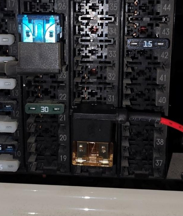
Insert the add-a-fuse into fuse position 31, ensuring it is fully seated.
Step 25 — Test the lights and reassemble the vehicle
Reconnect the driver-seat connectors and reinstall the driver seat, BCM support assembly, pedestal dust cover, floor insulation, kick plate, and battery cover. Reconnect the negative battery terminal.
Test the main beams and backlights to confirm that both sides function correctly. Reinstall the fender-liner clips and any remaining trim removed during the installation.
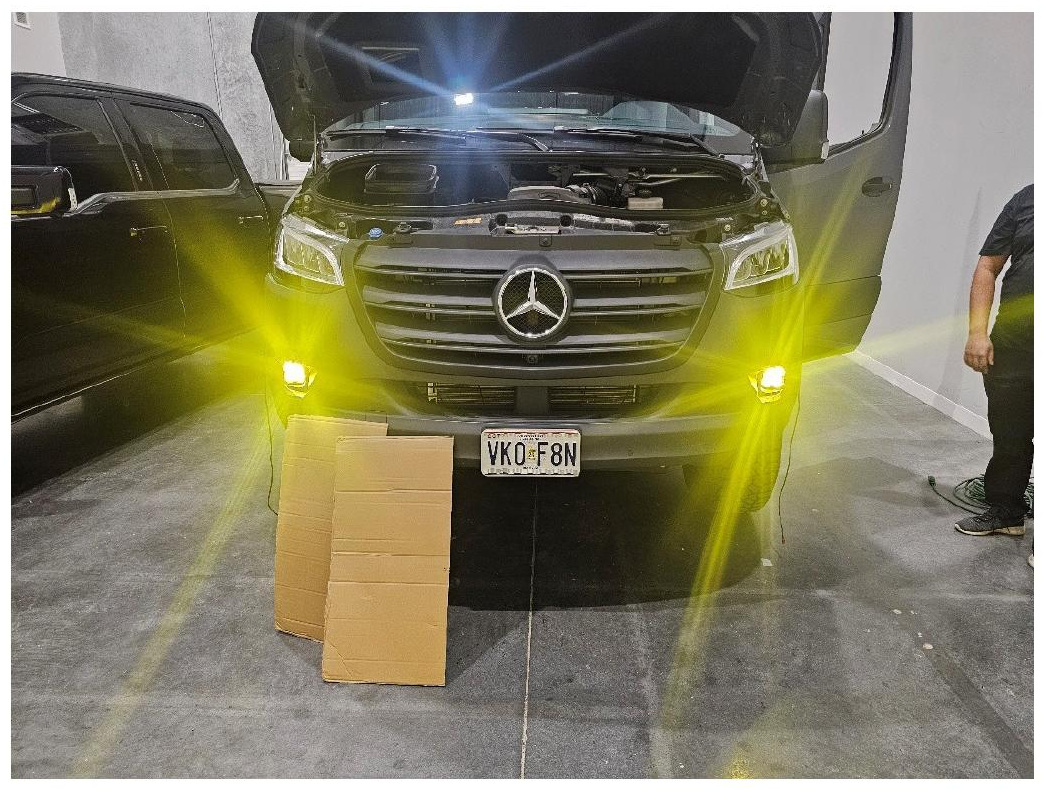
The installation is now complete. Enjoy your new SS3 LED Fog Light Kit for the 2019-2026 Mercedes-Benz Sprinter!
SmartSelect Programming
If your SS3 Fog Light Kit includes dual-color lamps, SmartSelect technology allows you to switch the main beam between white and yellow using the factory fog light controls. Single-color kits do not include SmartSelect programming and can skip this section.
Dual-color SS3 LED Pods are set to the white main beam from the factory. To enter programming mode, turn the fog lights ON for 1 to 3 seconds, then turn them OFF for approximately 1 second. Repeat this sequence two more times for a total of three ON and OFF cycles.
On the fourth ON sequence, the fog lights will begin toggling between white and yellow. Leave the fog lights ON when your desired color appears. After 5 seconds, the lights will save the selected color.
If the lights continue through two complete color cycles, they will enter Reset Mode and return to white. Yellow will not appear a third time. If this occurs, leave the fog lights ON to save white before attempting the programming sequence again. Turning the lights off without saving white will not exit Reset Mode.
Questions About the Installation?
If you have any questions about installing the SS3 LED Fog Light Kit for the 2019-2026 Mercedes-Benz Sprinter, contact us via our support page.
Where Can I Buy the SS3 LED Fog Light Kit for the 2019-2026 Mercedes-Benz Sprinter?
If you're ready to upgrade your 2019-2026 Mercedes-Benz Sprinter with the SS3 LED Fog Light Kit for the 2019-2026 Mercedes-Benz Sprinter, visit DiodeDynamics.com or use our Dealer Locator to find a dealer near you.
Want to know more about Diode Dynamics products? Visit DiodeDynamics.com and subscribe to our newsletter for new product releases and more!
This Installation Guide is for the following SKU: DD8971, DD8972, DD8973, DD8974, DD8975, DD8976, DD8977
Share This Post