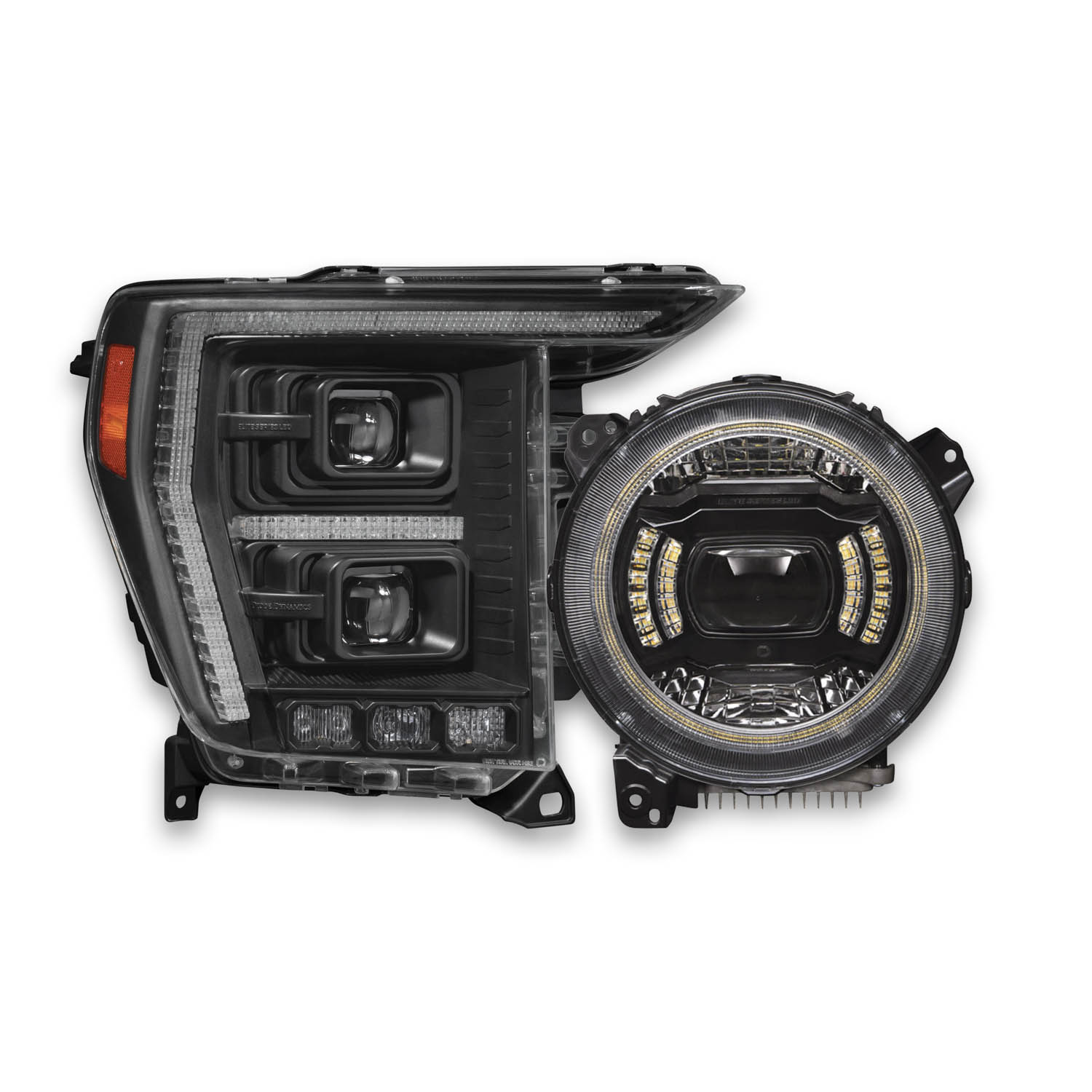


Elite Series Headlights have been designed for maximum performance both on and offroad. The following installation guide will provide you with detailed instructions for how to install Elite Series Headlights on the 2018+ Jeep JL Wrangler and 2020+ Jeep JT Gladiator. Check out our installation video, or continue reading for step-by-step instructions below!
Table of Contents
Installation Tools
- Ratchet
- Socket Extension
- 10mm Socket
- Plastic Trim Removal Tool
- Wire Crimper
Installation Video
Remove the Factory Headlights
Step 1 - Remove the Grille
Pop the hood and remove the six push rivets securing the grille to the vehicle using a plastic trim removal tool. Then remove the grille by grabbing the bottom and applying force, pull outward.

Step 2 - Remove the Headlight
Using a 10mm socket, remove the three bolts securing the stock headlight to the vehicle.

Step 3 - Disconnect the Factory Harness
Disconnect the factory headlight harness by pulling back on the red tab, pressing down on the tab, and prying the connector off. Repeat these steps on the other side of the vehicle.
Note: Some factory headlights may have a second connector for an OEM headlight leveling motor. This connector is not used with Elite Series Headlights. If present, leave it disconnected and secure it out of the way.

Route the Adapter Harnesses
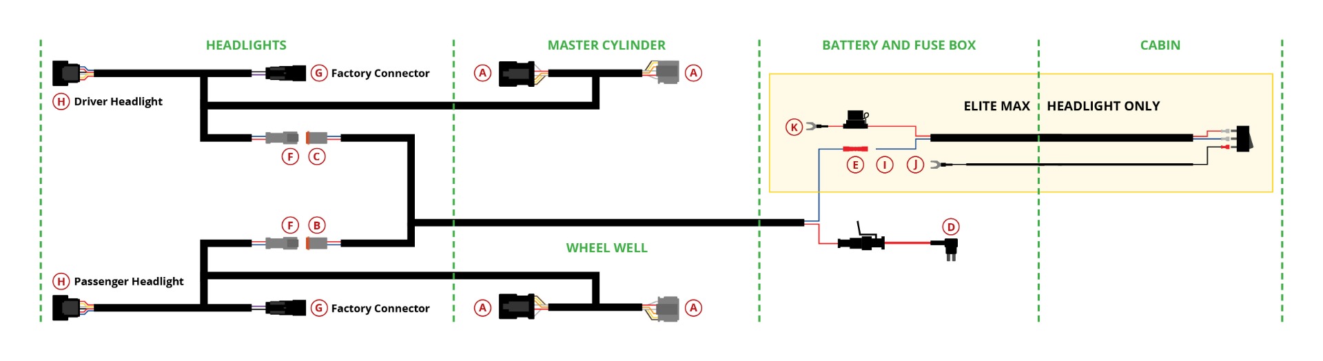
Step 4 - Route the Turn Signal Connectors
Starting on the driver's side of the vehicle, feed both turn signal connectors (A) from the included adapter harness through the headlight opening, along the fender, and behind the washer fluid reservoir. Then feed the connectors past the brake lines and A/C port.
Step 5 - Remove the Fuse Box
Remove the two 10mm bolts holding the smaller driver’s side fuse box in place. Move the fuse box to the side to give you better access to the factory connector.
Step 6 - Disconnect the Factory Connector
Locate the factory connector near the master cylinder on the underside of the fender. Remove it from the retaining clip holding it in place. Pull back the red locking tab on the connector to disconnect it.
Step 7 - Connect Turn Signal Connector on Driver's Side
Plug the turn signal connectors (A) from the adapter harness in line between the factory connector. Reattach the factory connector using the retaining clip removed in the previous step. Be sure to slide the locking tab back into the locked position.
Step 8 - Route Turn Signal Connectors on Passenger Side
On the passenger side of the vehicle, feed the turn signal connectors (A) on the second adapter harness and the air intake, along the fender, and between the battery and main fuse box.
Step 9 - Connect Turn Signal Connector on the Passenger Side
From the front passenger side wheel well, peel back the wheel well cover to gain access to the factory connector. Plug the turn signal connectors (A) from the adapter harness in line between the factory connector. Be sure to slide the locking tab back into the locked position.
Route the DRL & Auxiliary Tap Harness

Step 10
Route the shorter DT wire (B) from the auxiliary tap harness through the headlight opening on the passenger side of the vehicle. Leave it disconnected for now.
Step 11
Route the longer DT wire (C) from the auxiliary tap harness from the passenger side of the vehicle to the driver’s side. To do so, feed the DT wire through the passenger headlight opening, and under the radiator cover.
Feed the DT connector through the driver-side headlight opening, leaving it disconnected for now.
Step 12
Route the power side (D) (E) of the auxiliary tap wiring harness from the passenger side of the vehicle to the fuse box. To do so, feed the harness through the passenger headlight opening, along the right side of the air intake, and to the left side of the battery.
Step 13
Open the fuse box. Remove the 20A cigarette lighter fuse in slot F52 and insert it into the first empty slot on the add-a-fuse wire (D) on the auxiliary tap harness. Then install the add a fuse wire back into slot F52. Close the fuse box with the red wire exiting towards the battery.
Step 14 - Wire Offroad Lighting Feature (Elite Max Model Only)
If you purchased the Elite Max model, wire up the offroad lighting feature using the instructions below:
Method One - Factory-Installed Switch Bank
If you plan to control the offroad lights with a factory-installed switch bank, crimp the butt connector (E) on the auxiliary tap harness, to a switch bank wire lead found near the battery. Any wire can be used – refer to your owner’s manual to determine which wire color corresponds with which switch.
Method Two – Install Toggle Switch
If you plan to control the offroad lights through the included toggle switch, connect the bare wire lead (I) on the toggle switch adapter wire to the butt connector (E) on the auxiliary tap harness using a crimping tool.
Connect the spade terminals on the switch wire to the toggle switch. The black wire should connect to the gold terminal and the blue wire should connect to the middle terminal. Then, attach the split ring terminal (J) to a factory grounding point.
Connect the fused split ring terminal (K) on the switch wire to the positive battery terminal.
Determine a suitable location to mount the switch in the cabin of the vehicle. Route the switch wiring to that location. This may require going through the vehicle firewall. We recommend following the path of the factory wiring harness, and unplugging the switch while routing the wires.
Drill a ¾” hole and mount the switch. Reconnect wires to the switch, with the red wire in the center position.
Wire the Headlights
Step 15 - Plug in the Headlights
Plug the DT connector (B) (C) from the auxiliary tap harness into the DT connector (F) on the adapter harness. Plug the headlight connectors (G) (H) in line between the factory headlight connector and your new Elite headlight.
Be sure to push the red locking tab down. Repeat for the other side of the vehicle.
Step 16 - Install the Headlights
Install your new Elite Headlights onto the vehicle using the original factory bolts.
Step 17 - Aim the Headlights
Test the function and aim the headlights. If adjustments are needed, use the included adjuster tool.
Aiming Video
For aiming instructions, you can watch the video below.
Note: It should only be necessary to aim the headlights using the "Down Up" adjustment screw as shown below. It is not recommended to alter the setting of the left and right adjustment screws since Elite Series Headlights are set to be straight before leaving the factory.

Step 18 - Reinstall the Grille
Once the headlights have been aimed, reinstall the grille and secure it with the original push rivets.
Step 19 - Enable Headlight Illumination On Approach Feature
Make sure the Jeep's "Headlight Illumination On Approach" feature is enabled.
To do so, tap the "Settings" button on the Uconnect touchscreen display. Then select the "Lights" setting.
Use the plus and minus touchscreen buttons to set the "Headlight Illumination On Approach" to 30, 60, or 90 seconds.
Do not leave it at 0 seconds, as that disables the feature.
Exit the "Lights" setting tab to save your selection.
Programming Instructions
If desired, follow the instructions in the video below, or check out our step-by-step programming guide to select your DRL and Show Mode.
Questions About the Installation?
If you have any questions or issues installing the Elite Series Headlights in your JL Wrangler or JT Gladiator, please contact us for further assistance.
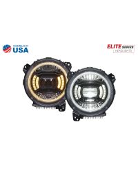
Where Can I Buy Elite Series Headlights?
If you’re ready to upgrade your JL Wrangler or JT Gladiator with Elite Series Headlights, you can purchase them by clicking here or using our dealer locator to find a dealer near you.
Want to know more about Diode Dynamics products? Visit DiodeDynamics.com and subscribe to our newsletter for new product releases and more!
This Installation Guide is for the following SKUs: DD5165, DD5166

Share This Post