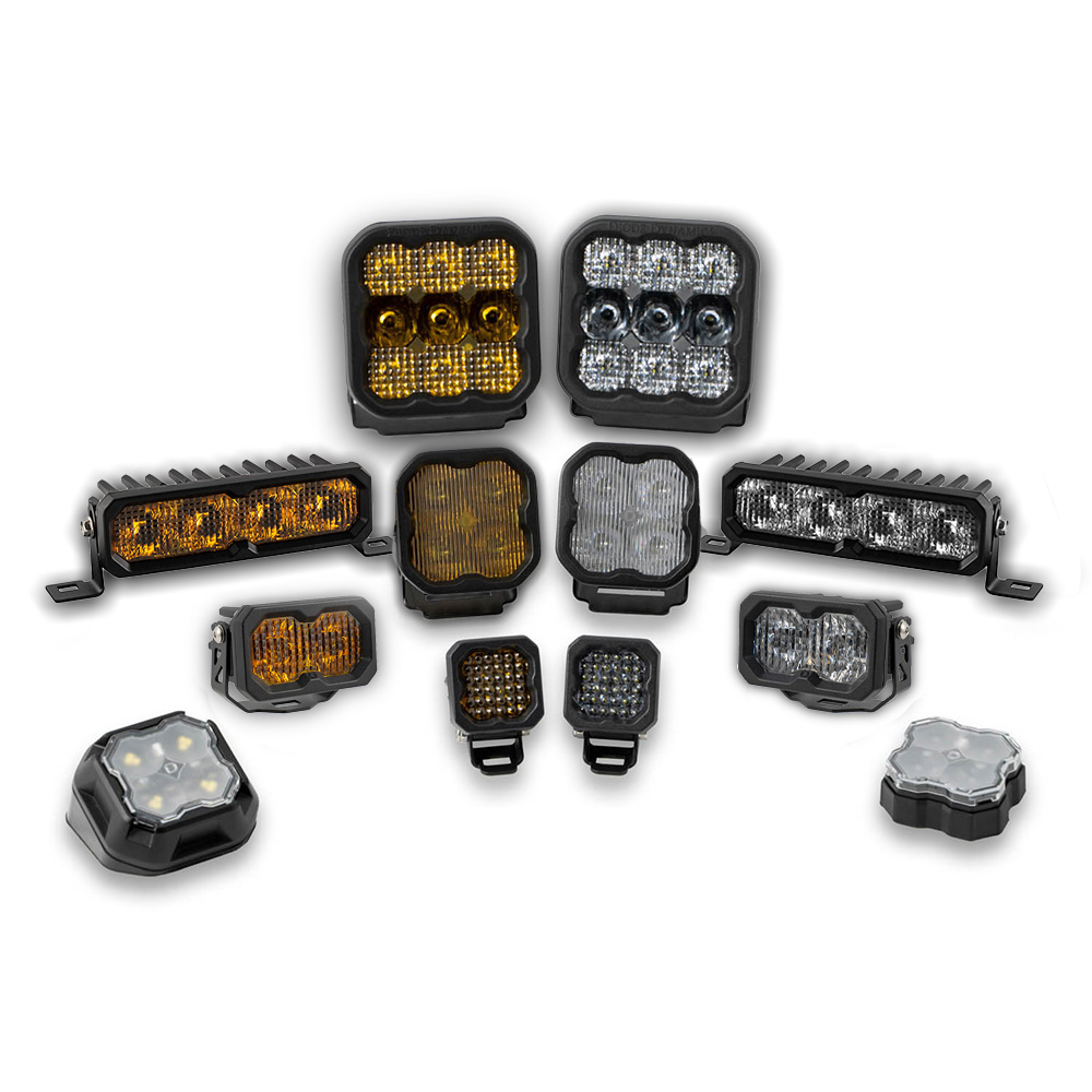
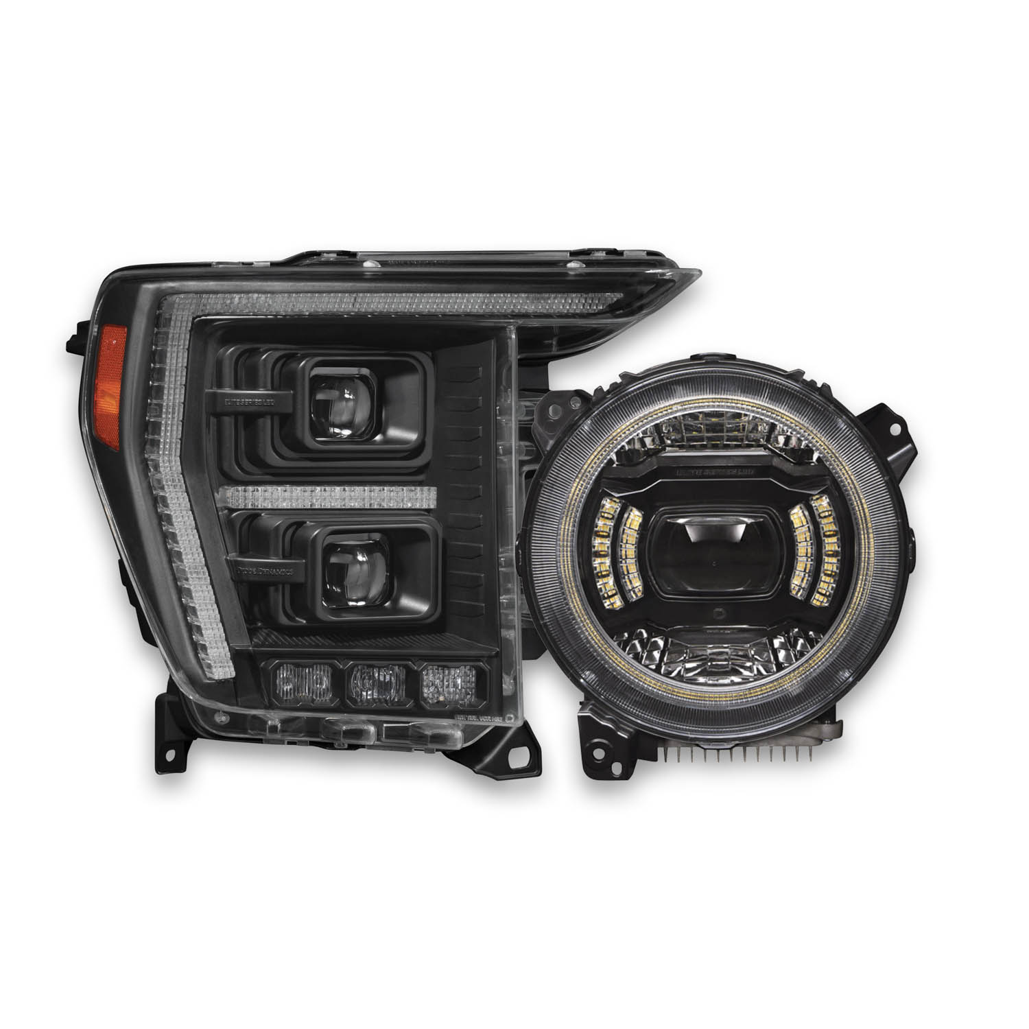
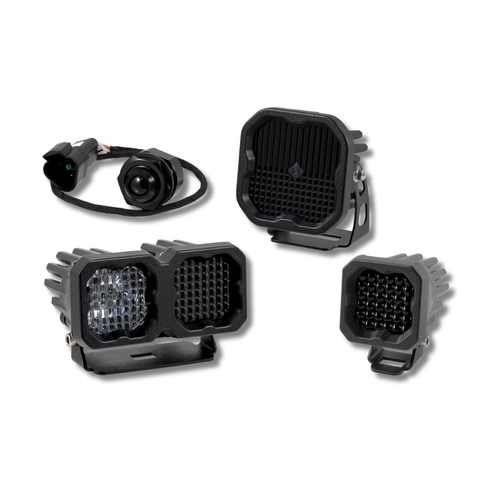



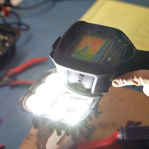
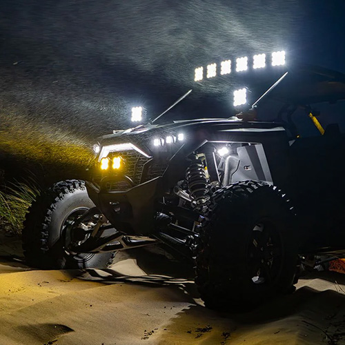
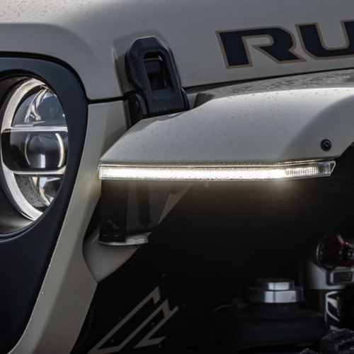

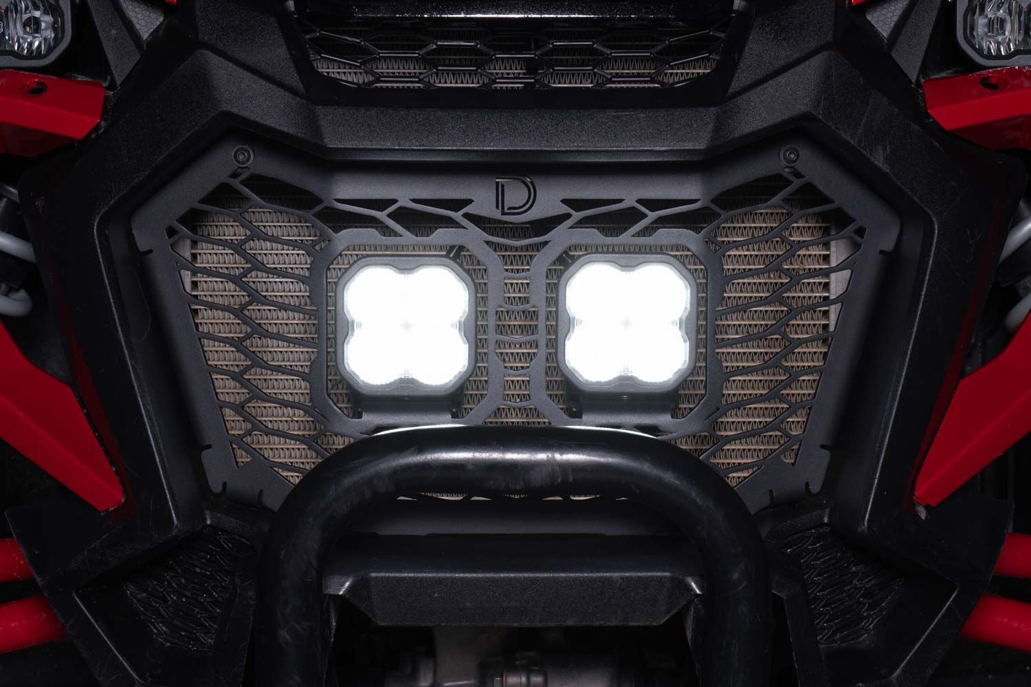
Looking to improve visibility on your 2022-2025 Honda Talon? The SS3 LED Grille Kit replaces the factory grille and adds two SS3 LED Pods, while the SS10 LED Grille Kit pairs a replacement metal grille with one SS10 LED Light Bar. Both direct-fit kits provide a clean, integrated appearance and powerful off-road lighting. This installation guide covers both versions. Watch the installation video or continue reading for detailed instructions below!
Table of Contents
Installation Video
Installation Tools
- 10mm socket and wrench
- 4mm Allen wrench
- 5mm Allen wrench
- Phillips head screwdriver
- Flathead screwdriver
- Plastic trim removal tool
- Zip ties
Installation time: approximately 60-90 minutes.
What's Included
The components used during installation depend on the kit selected.
- SS3 LED Grille Kit: Replacement grille bracket, two SS3 LED Pods, DT splitter, application-specific mounting hardware, and wiring harness.
- SS10 LED Grille Kit: Replacement grille bracket, one SS10 LED Light Bar, DT extension, application-specific mounting hardware, and wiring harness.
Verify the contents of your kit against the included packing list before beginning installation.
Installation Instructions
Step 1 - Remove the Hood
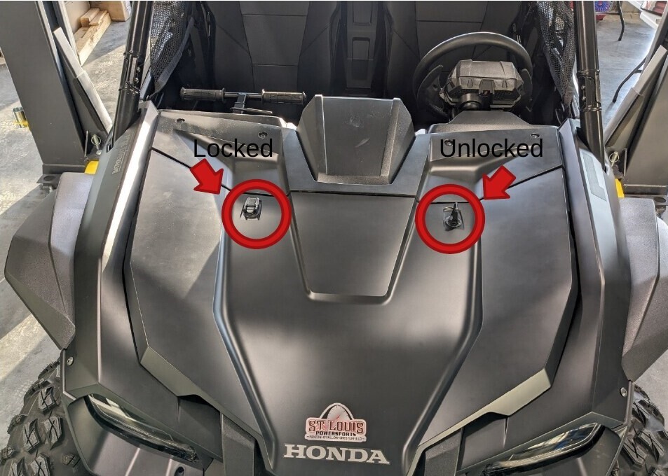
Pull up and rotate both hood latches to the unlocked position. Firmly lift the hood at the molded hand indents, then pull the hood toward the front of the vehicle to remove it.
Step 2 - Disconnect the Headlight Harness
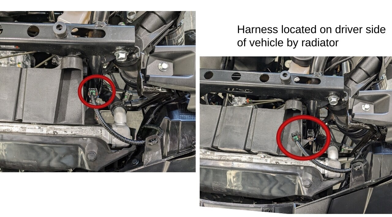
Locate the headlight harness near the radiator on the driver side. Depress the locking clip and pull the connector upward to disconnect it.
Step 3 - Remove the Firewall Shield and Cowl
On the passenger-side fender, carefully release the coolant hose from the plastic retaining hooks. Locate the black rubber shield along the firewall and remove the eight plastic clips with a flathead screwdriver or trim removal tool.
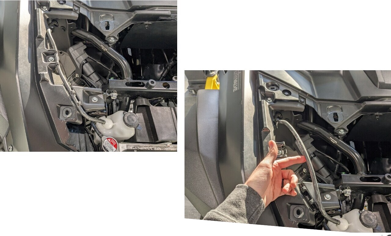
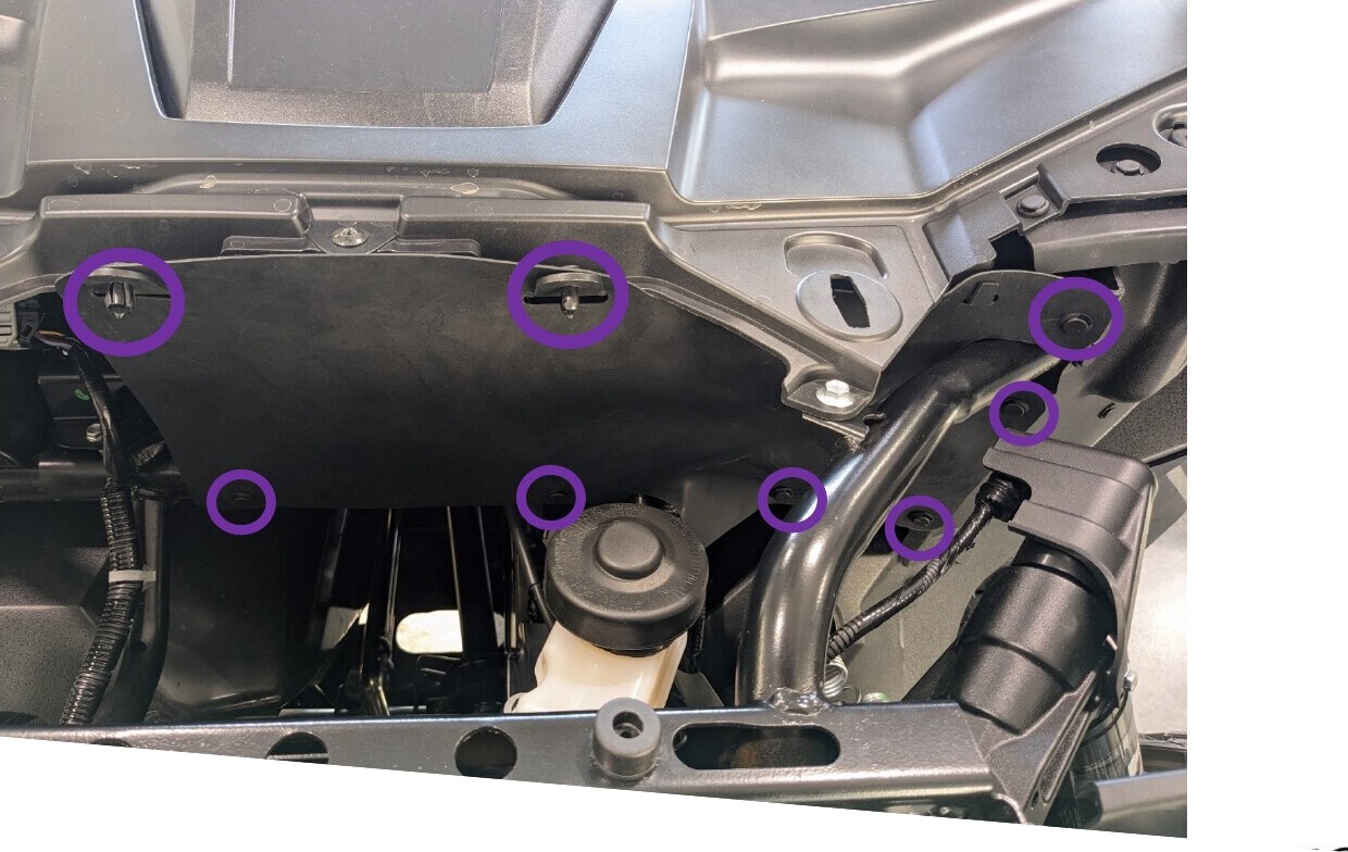
Remove the four plastic clips, four 10mm bolts, and five 5mm Allen bolts securing the cowl. Lift the cowl from the vehicle and set it aside.
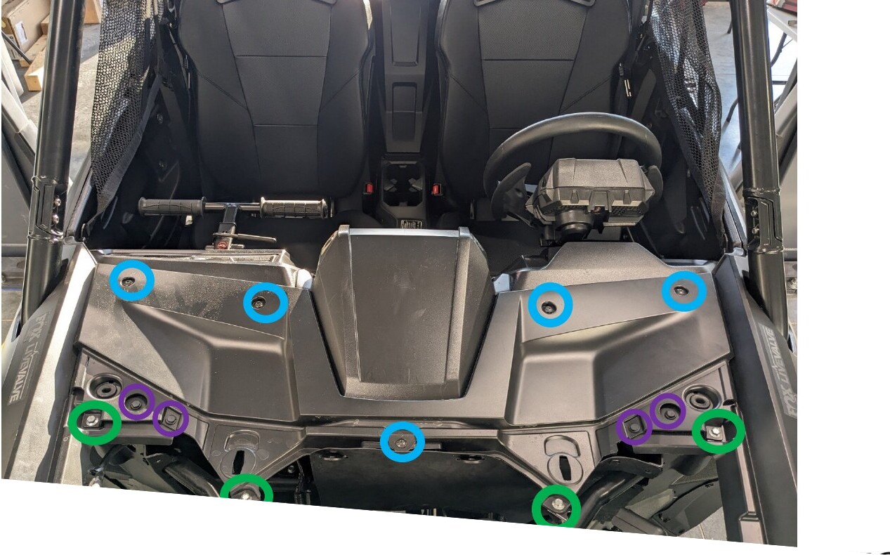
Step 4 - Release the Fenders and Headlight Shrouds
Remove the four 10mm bolts from the fenders. On each side, remove the 5mm Allen bolt and plastic clip from the headlight shroud. Remove the additional plastic clip behind each headlight bucket and the clip at the inside corner of each headlight shroud.
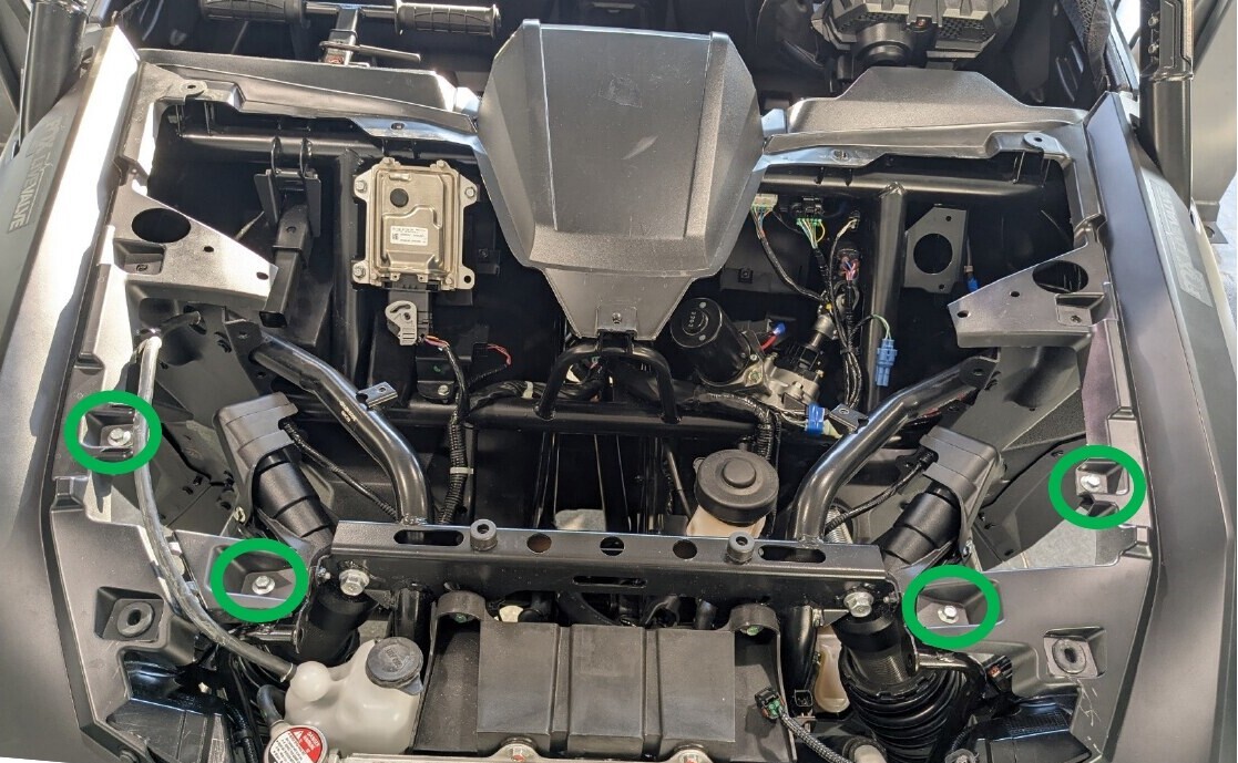
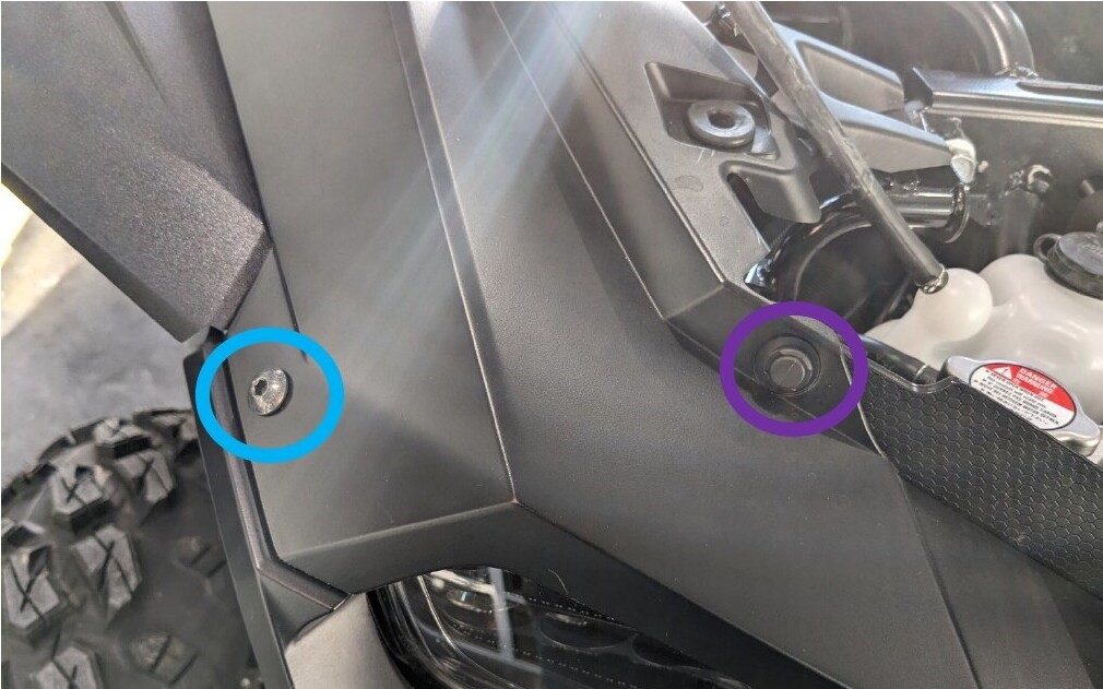
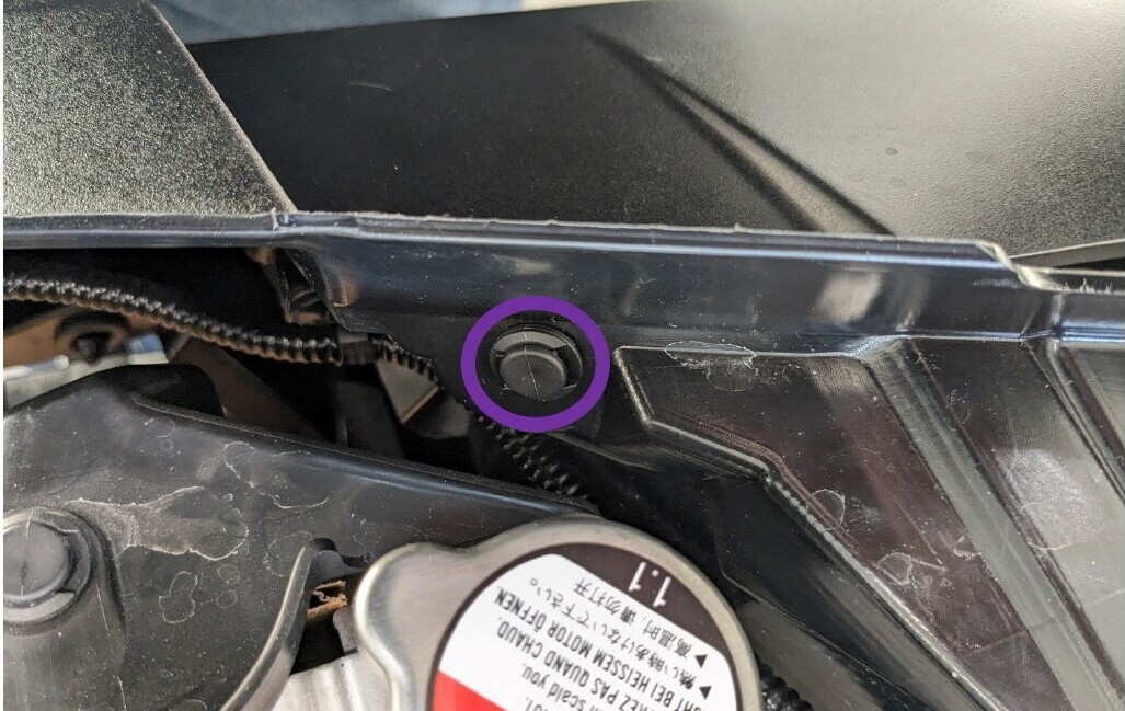
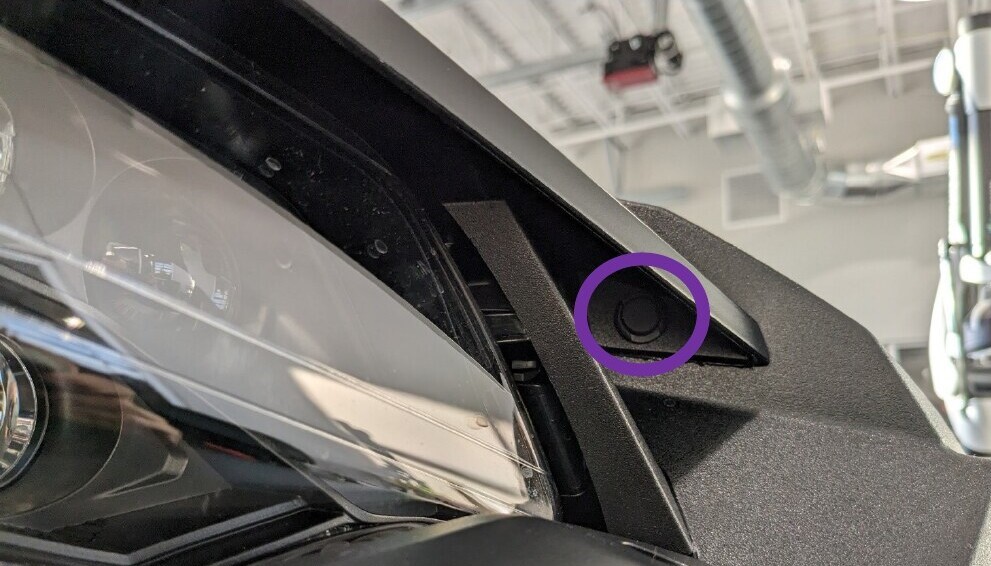
Move the coolant hose clear of the passenger-side fender bracket. Lift the fender, route the hose beneath the plastic fender bracket, and set the fender back into position.
Step 5 - Remove the Front Bumper
Remove the 10mm bolt from each side of the front bumper. Remove the two plastic clips securing the bottom of the bumper to the skid plate.
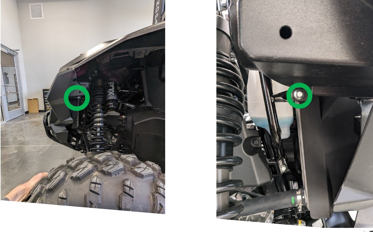
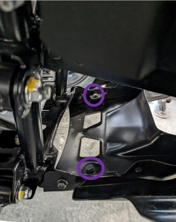
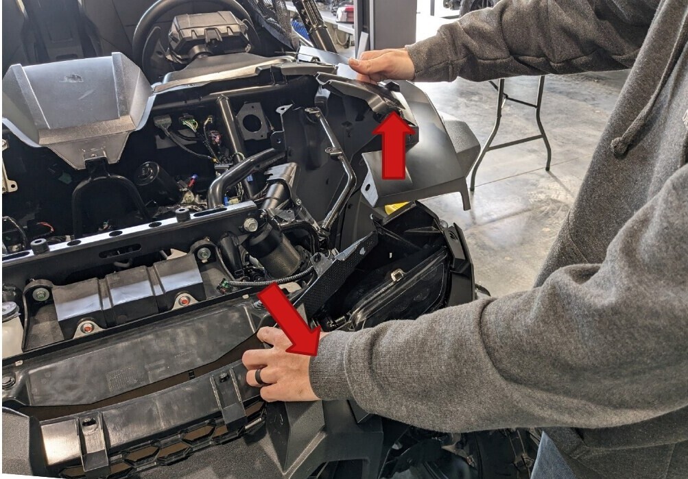
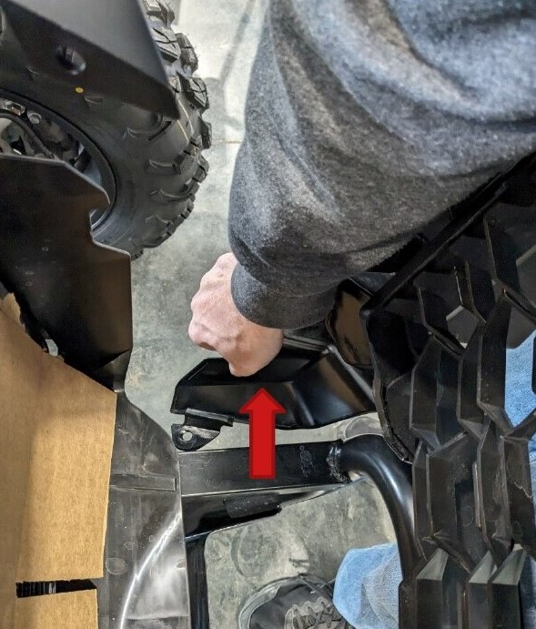
Lift one fender and pull that side of the bumper toward the front of the vehicle, then repeat on the opposite side. Pull the lower plastic tabs around the metal bull bar on both sides and remove the bumper. Place the bumper on a protected work surface to prevent damage.
Step 6 - Remove the Factory Grille
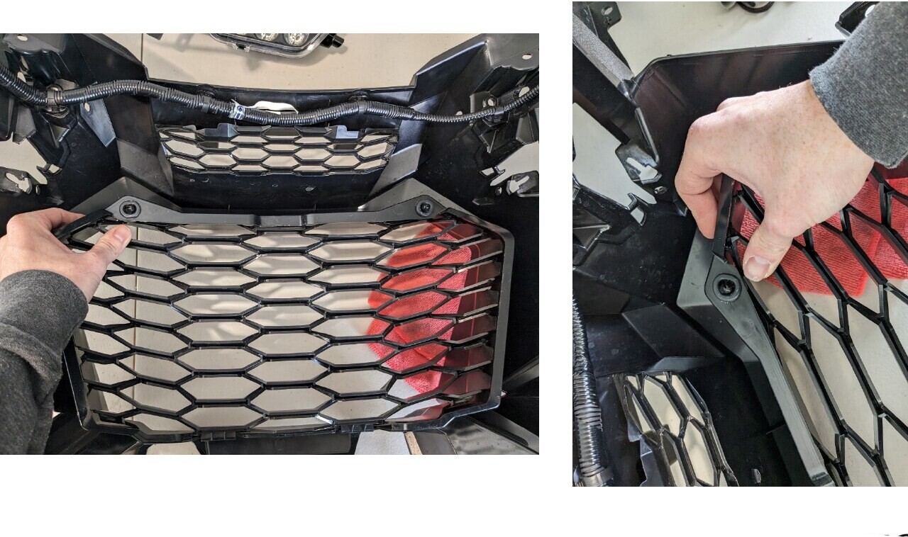
From the back of the bumper, push firmly near each upper corner of the factory grille to release the ball clips. Remove the factory grille from the front of the bumper and set it aside.
Step 7 - Install the Lights in the Replacement Grille
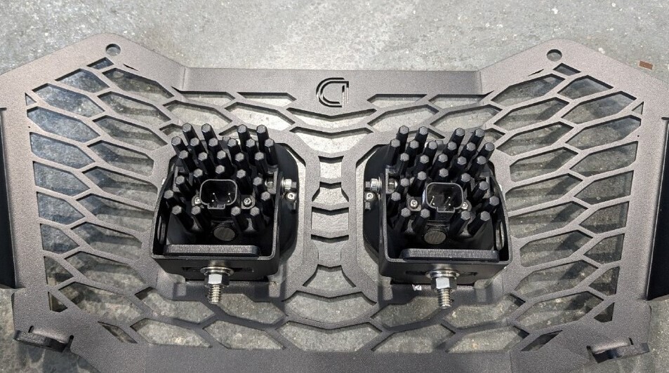
SS3 LED Grille Kit: Slide each SS3 bracket beneath the grille mounting tabs. Insert the carriage bolts from the top, then install the supplied washers, lock washers, and nuts. Tighten the hardware to secure both SS3 LED Pods.
SS10 LED Grille Kit: Insert the SS10 LED Light Bar through the front of the replacement grille. Install the supplied 10mm mounting bolts into the ends of the light bar. Leave the bolts slightly loose until the light bar is centered, then tighten the hardware.

Step 8 - Install the Replacement Grille
Align the lower tabs of the replacement grille with the slots in the bumper. Set the grille into place and align the two upper mounting holes.
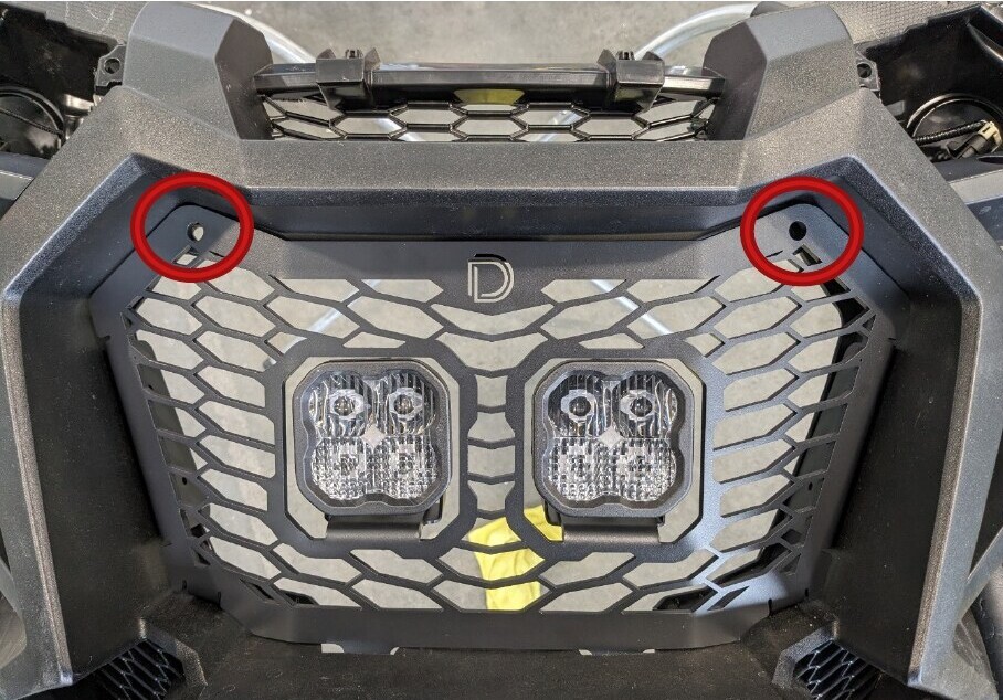
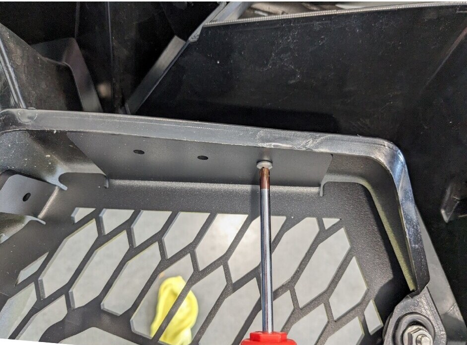
Install the supplied bolts and flange nuts in the two upper holes. The appearance of this hardware may differ slightly from the hardware shown. Install the eight Phillips head screws through the grille bracket holes. Tighten the screws until secure, but do not overtighten them.
Step 9 - Connect the Front Light Wiring
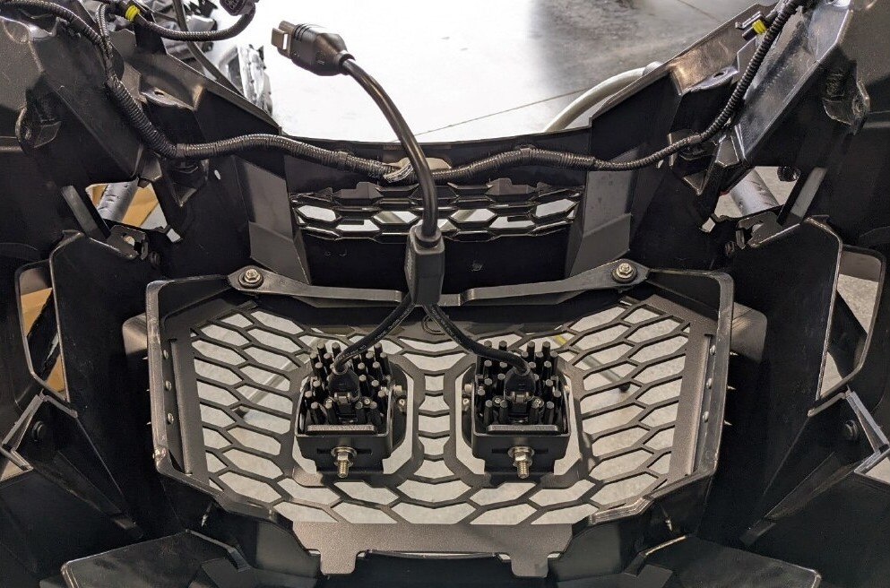
SS3 LED Grille Kit: Connect both SS3 LED Pods to the included DT splitter.
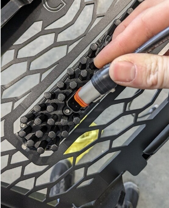
SS10 LED Grille Kit: Connect the included DT extension directly to the SS10 LED Light Bar.
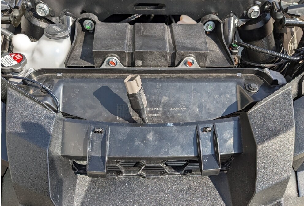
Temporarily position the bumper on the vehicle. Route the splitter or extension from the top of the bumper near the radiator so it remains accessible for connection to the main wiring harness.
Step 10 - Remove the Seats and Center Console
Pull the latch beneath the passenger seat bottom and remove the seat.
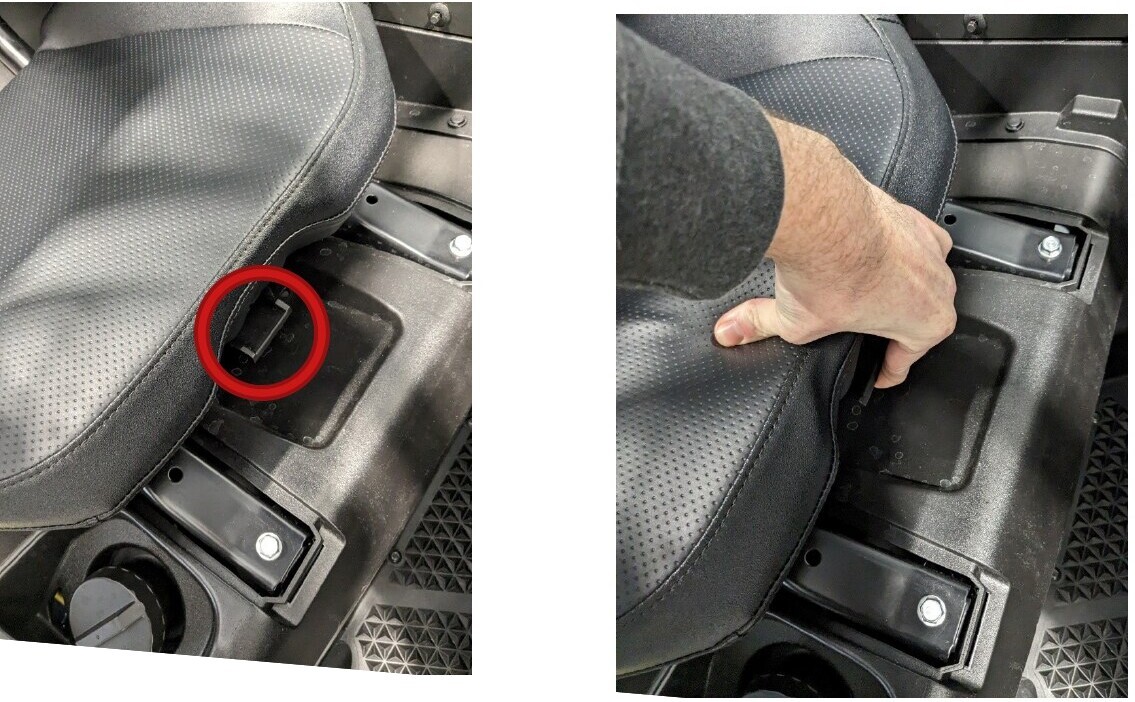
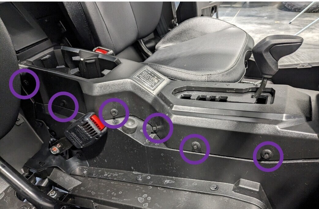
Pivot the passenger seat belt latch toward the front of the vehicle, then remove the six plastic clips from the passenger side of the center console.
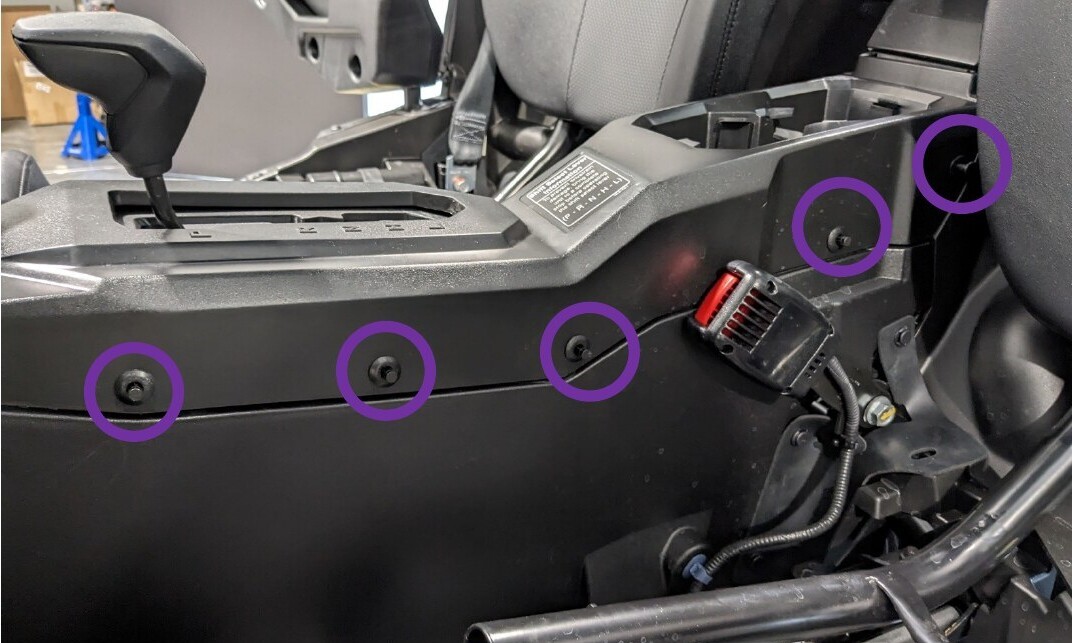
Remove the driver seat bottom in the same manner. Pivot the driver seat belt latch forward and remove the five plastic clips from the driver side of the center console.
With the brake applied, move the transmission selector from Park to Reverse to create clearance. Lift the rear of the center console, then lift and pull the console rearward to remove it from the vehicle.
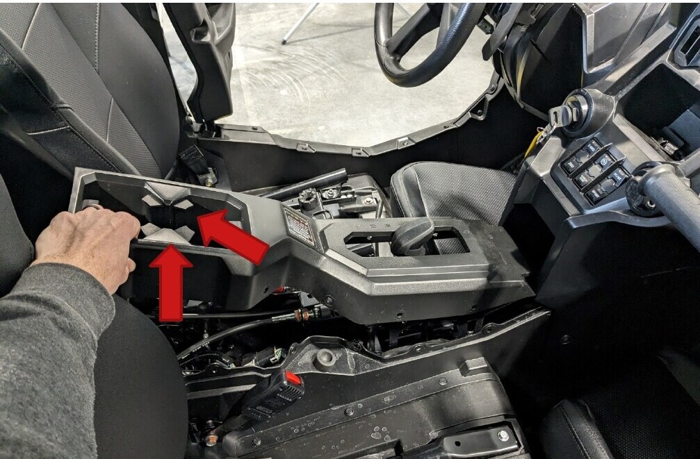
Step 11 - Access the Battery
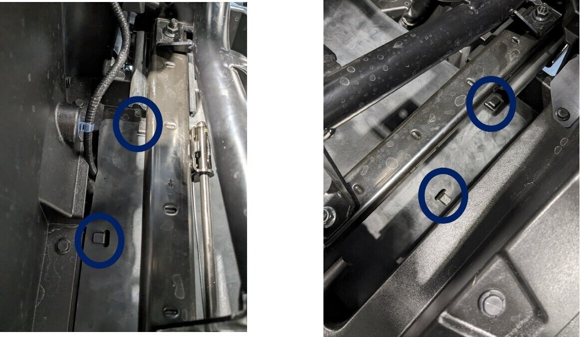
On the driver side, locate the rubber cover beneath the seat. Release it from the four plastic hooks and roll it forward out of the way.
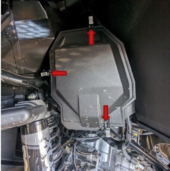
Locate the battery box behind the driver seat in the engine compartment. Push the metal retaining clips in the direction shown and pull the battery box lid toward you to remove it.
Step 12 - Connect the Wiring Harness to the Battery
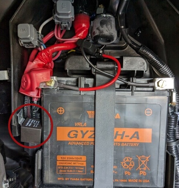
Route the positive and negative leads from the wiring harness to the top of the battery. Connect the positive lead to the positive battery terminal and the negative lead to the negative battery terminal.
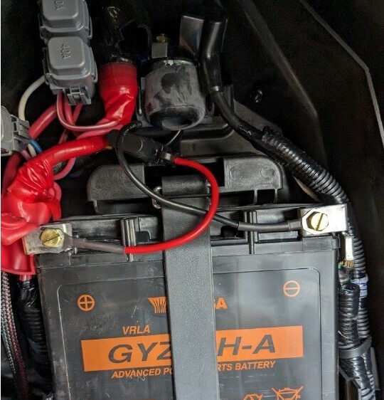
Route the relay alongside the battery and reinstall the battery box lid. If the vehicle has multiple wiring harnesses, the battery box may not have enough room to hold every relay. Secure any additional relays in a protected location nearby.
Step 13 - Route the Harness into the Cabin
Locate the factory wire loop below the battery box and release its clip with a flathead screwdriver. Route the wiring harness through the loop, then pass it through the opening at the rear of the firewall and into the driver-seat area.
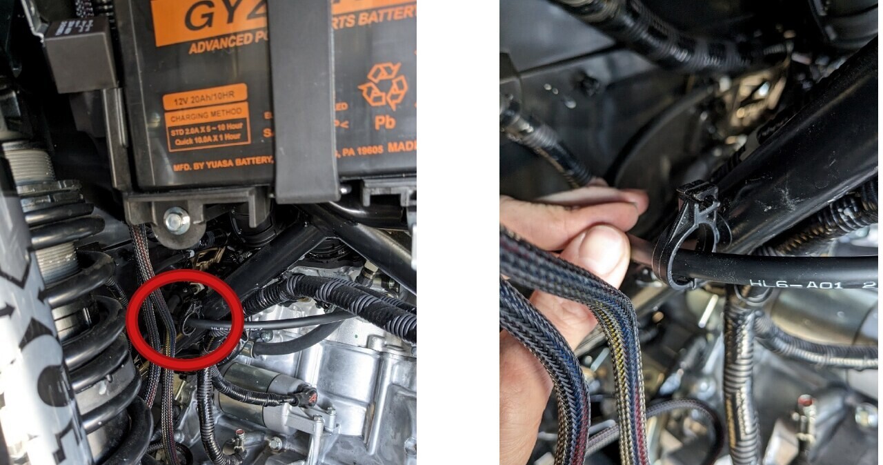
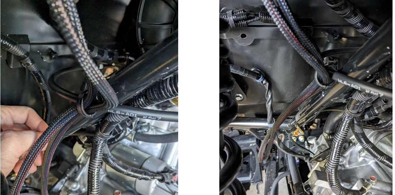
Pull the harness into the cabin and route it beneath the seat frame toward the seat belt latch. Keep the harness clear of sharp edges, hot components, and moving parts.
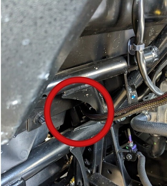
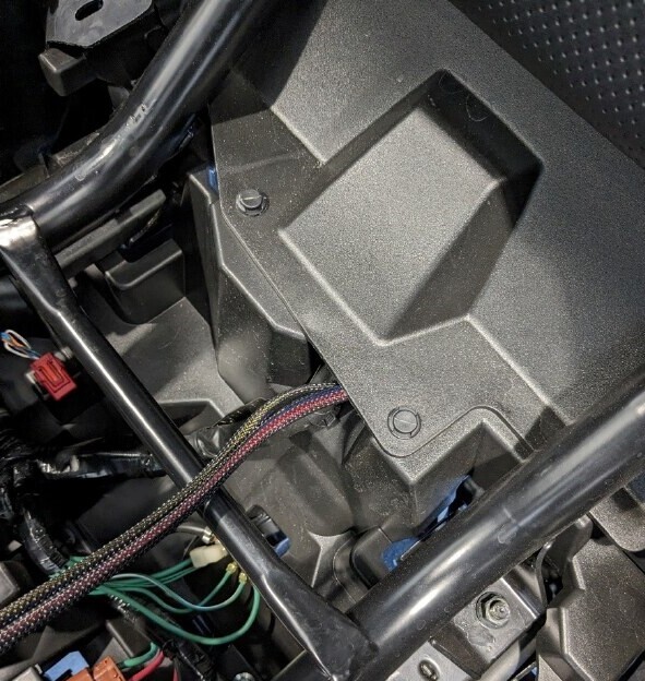
Step 14 - Route the Harness Through the Center Console
Route the harness through the opening in the center console near the driver seat belt latch. Continue forward through the console and around the transmission selector. Keep all wiring away from the driveshaft beneath the black center tubing.
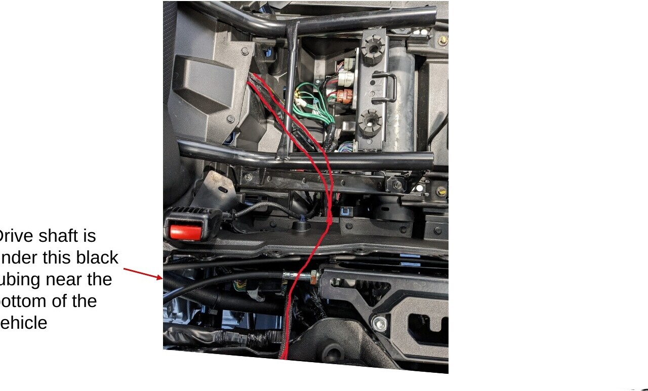
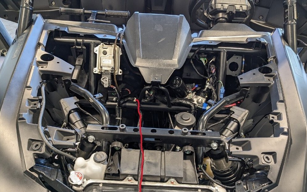
From the front of the vehicle, pull the light-output lead toward the radiator. Leave the switch lead inside the cabin for the next step.
Step 15 - Install the Harness Switch
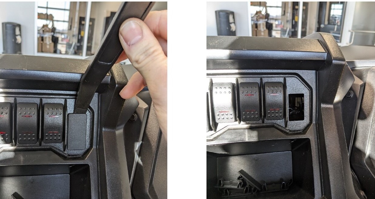
Choose a convenient switch location. The supplied toggle switch can be installed by drilling a suitable hole in a factory switch blank, or it can be mounted in another location of your choice. Remove the selected blank with a plastic trim tool and route the switch lead beneath the raised section of the dash to the mounting location. Install the switch and connect it to the harness.
Step 16 - Install the Rectangular Rocker Switch (Optional)
The Diode Dynamics Rectangular Rocker Switch can be used with the Heavy Duty or Ultra Heavy Duty relay harness. Disconnect the supplied toggle switch by separating the white inline connector on the switch lead. Connect the rectangular rocker switch directly to the harness-side white connector.
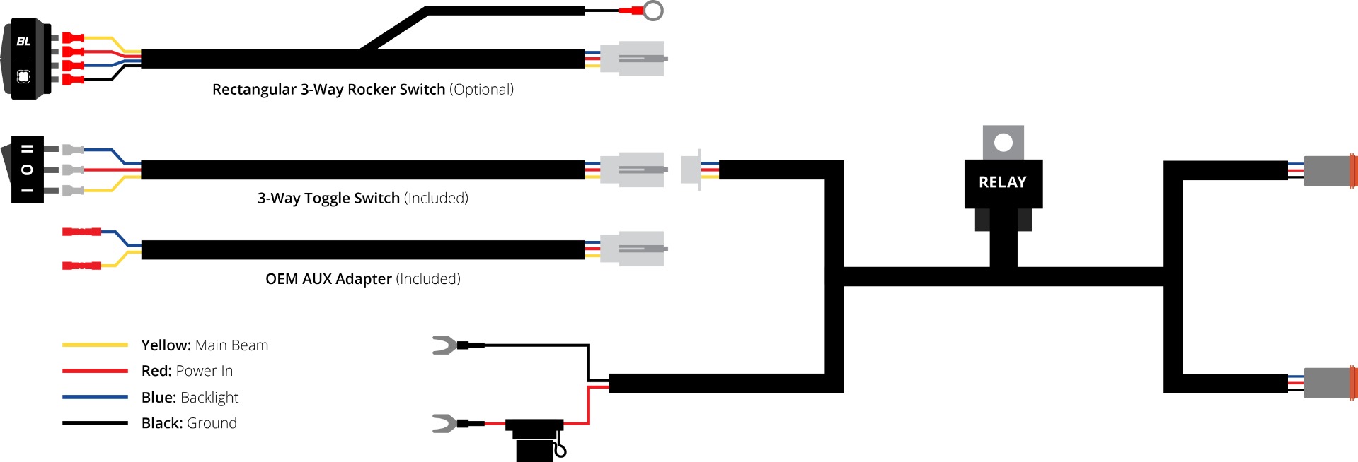
Remove the desired factory switch blank and insert the rocker switch until fully seated. Route the switch wiring away from sharp edges and moving components. The rocker switch requires a ground connection for its integrated backlight. Attach the black wire with the ring terminal to a suitable chassis ground.
Step 17 - Connect and Test the Lights
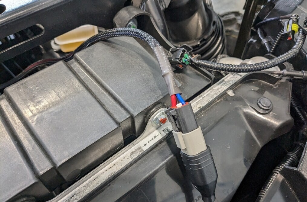
At the front of the vehicle, connect the main harness DT lead to the SS3 splitter or SS10 DT extension near the radiator. Turn on the lights and confirm that they operate correctly before reassembling the vehicle.
Step 18 - Reassemble the Vehicle
Secure the wiring with zip ties and confirm that it remains clear of the driveshaft, steering components, suspension components, hot surfaces, and sharp edges.
Reinstall the rubber cover beneath the driver seat. Reinstall the center console, return the transmission selector to Park, and reinstall the console clips, seat belt latches, and both seat bottoms.
Reinstall the cowl with its four plastic clips, four 10mm bolts, and five 5mm Allen bolts. Reinstall the eight clips securing the rubber firewall shield. Reconnect the headlight harness, confirm that the coolant hose is secured in its original retaining hooks, and reinstall the front bumper.
Position the hood on the vehicle and press it into the rubber mounting clips. Rotate both hood latches to the locked position.
Aiming Instructions
Park the vehicle on a level surface facing a wall or garage door. Loosen the light mounting hardware slightly, adjust the SS3 LED Pods or SS10 LED Light Bar to the desired vertical position, and tighten all mounting hardware. Confirm the beam position before operating the vehicle.
The installation is now complete. Enjoy your new SS3 LED Grille Kit or SS10 LED Grille Kit!
Questions About the Installation?
If you have any questions about installing the SS3 LED Grille Kit for the 2022-2025 Honda Talon or SS10 LED Grille Kit for the 2022-2025 Honda Talon, contact us through our support page.
Where Can I Buy the SS3 or SS10 LED Grille Kit for the 2022-2025 Honda Talon?
If you're ready to upgrade your 2022-2025 Honda Talon, purchase the SS3 LED Grille Kit or SS10 LED Grille Kit at DiodeDynamics.com. You can also use our Dealer Locator to find a dealer near you.
Looking for more lighting options for your Talon? Browse our complete selection of Honda Talon lighting upgrades.
Want to learn more about Diode Dynamics products? Visit DiodeDynamics.com and subscribe to our newsletter for new product releases and more!
This installation guide is for the following SKUs: DD7899, DD7903, DD7900, DD7904, DD7901, DD7905, DD7902, DD7906, DD7898, DD7926, DD7927, DD7922, DD7923, DD7928, DD7929, DD7924, DD7925, DD8345, DD8346, DD8343, DD8344, DD7921P
Share This Post