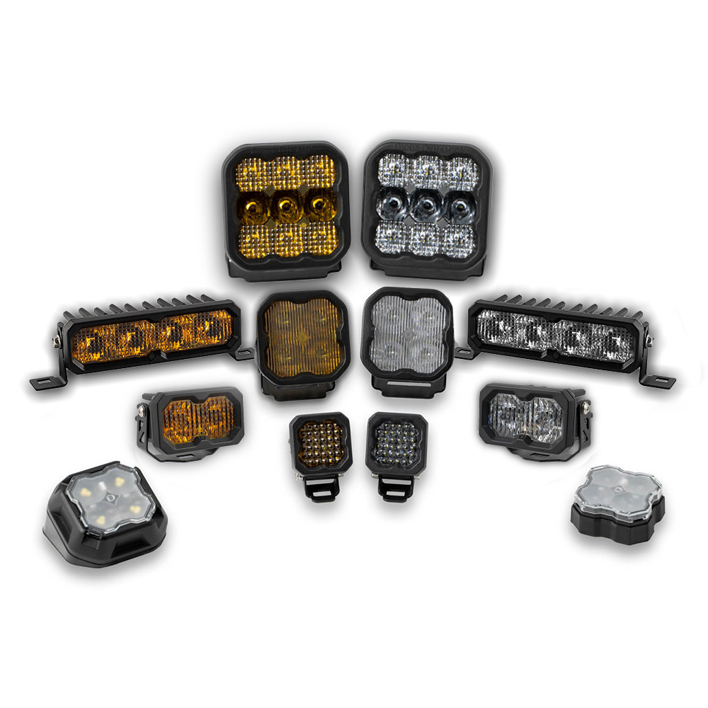


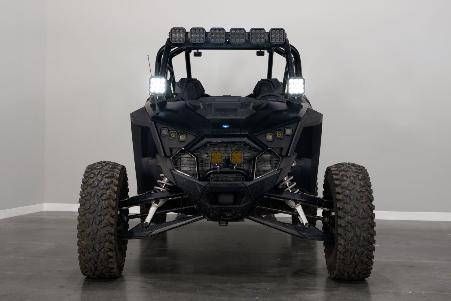
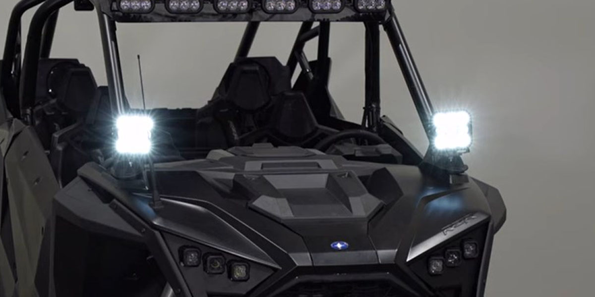
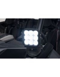
The Stage Series A-Pillar LED Pod Kit for the 2020+ Polaris RZR Pro allows you to easily mount two SS5 or SS3 LED Pods to the A-Pillars of your UTV. This kit provides a custom off-road appearance and a powerful increase in light output for nighttime rides and better visibility in dusty conditions.
In addition to the high light output, the SS5 LED Pods included in this kit feature eight selectable backlight colors. You can easily toggle between them with the included switch whenever the main beams are not in use.
The following installation guide will provide you with detailed instructions on how to install the Stage Series A-Pillar LED Pod Kit for the 2020+ Polaris RZR Pro. Check out our installation video or continue reading for step-by-step instructions below!
Table of Contents
Installation Video
Installation Tools
- 3/8" Ratchet
- 3" Ratchet Extension
- 18mm Socket
- 18mm Wrench
- Razor Blade/Knife
- Bubble Level
- Tape Measure
- T40 Torx Driver
- 1/8" Drill Bit
- Stepping Drill Bit
- Cordless Drill/Driver
- Flush-Cut Pliers
Installation Instructions
Step 1 - Remove the Driver Seat Adjustment Buckles.
Begin removing the driver seat by undoing both of the adjustment buckles with the red pull tabs.

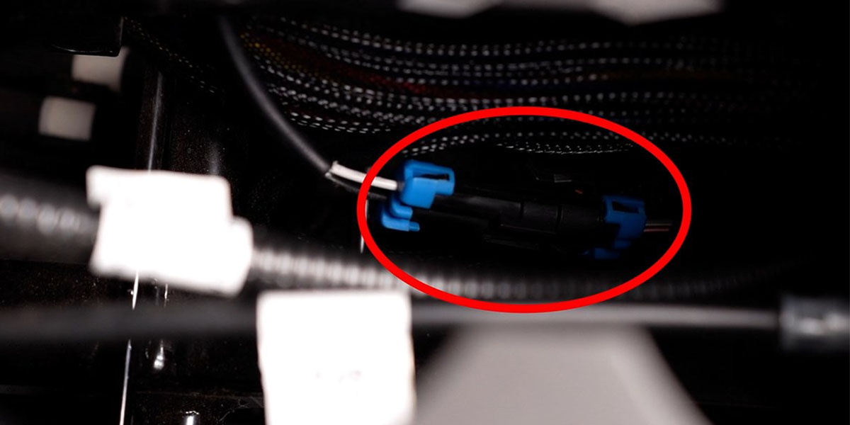
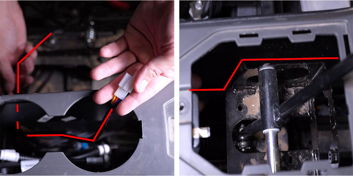
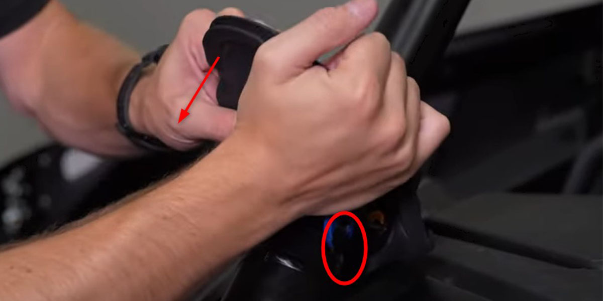
Step 2 - Disconnect Connector Under Cup Holders.
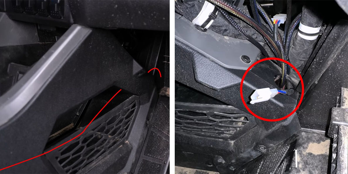
Use a plastic trim removal tool to pry up the front of the plastic cup holder and pop it out of place. Once removed, set the cup holder aside.
Looking down into the area where the cup holder was, locate the connector with blue tabs (circled in red). Reach in and disconnect it. Then feed the end that attaches to the safety harness out from under the center console and towards the driver seat.
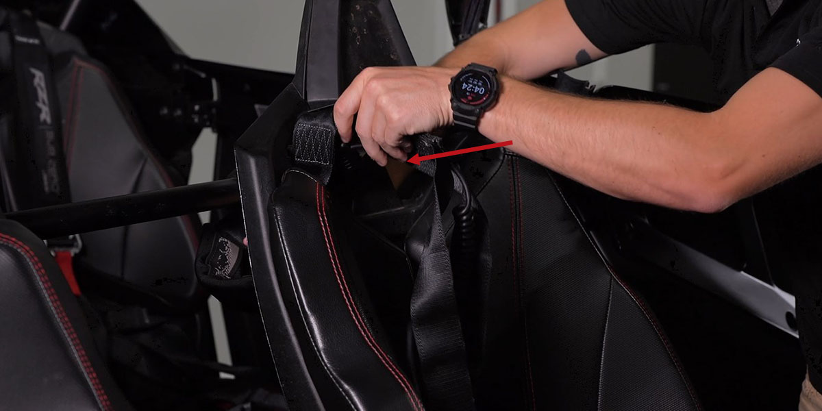
Step 3 - Remove Driver-Seat Safety Harness.
Feed the safety harness through the back of the driver's seat.
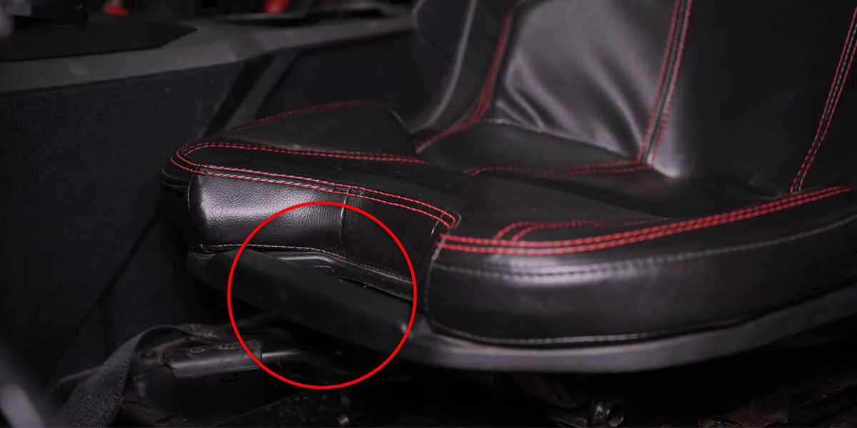
Step 4 - Remove the Driver's Seat.
Remove the driver's seat by pulling the release handle (circled in red) and tilting the seat forward, up, and out of the vehicle.
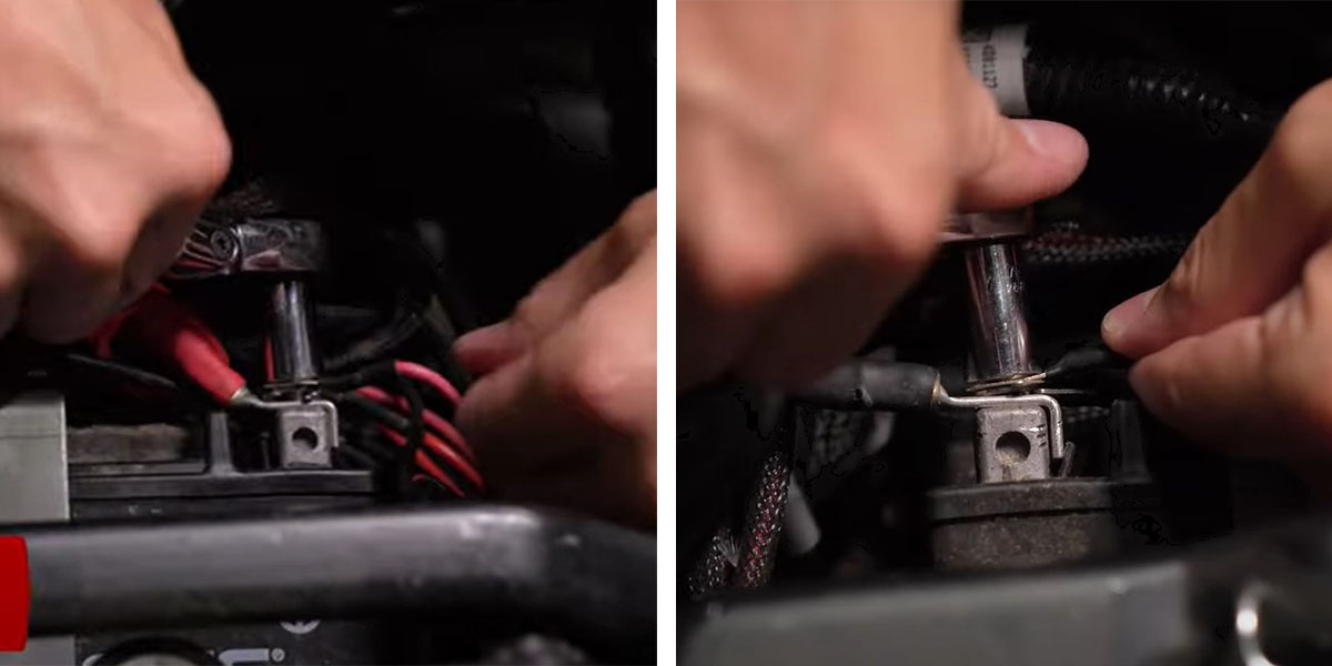
Step 5 - Connect Battery.
Use a 10mm socket to connect the red wire from our harness to the positive battery terminal and the black wire to the negative battery terminal. Then tuck the relay next to the battery so it is out of the way.
Step 6 - Remove Center Console Bolts.
With a 10mm socket, remove the four bolts (circled in red) along the bottom of the driver's side of the center console.
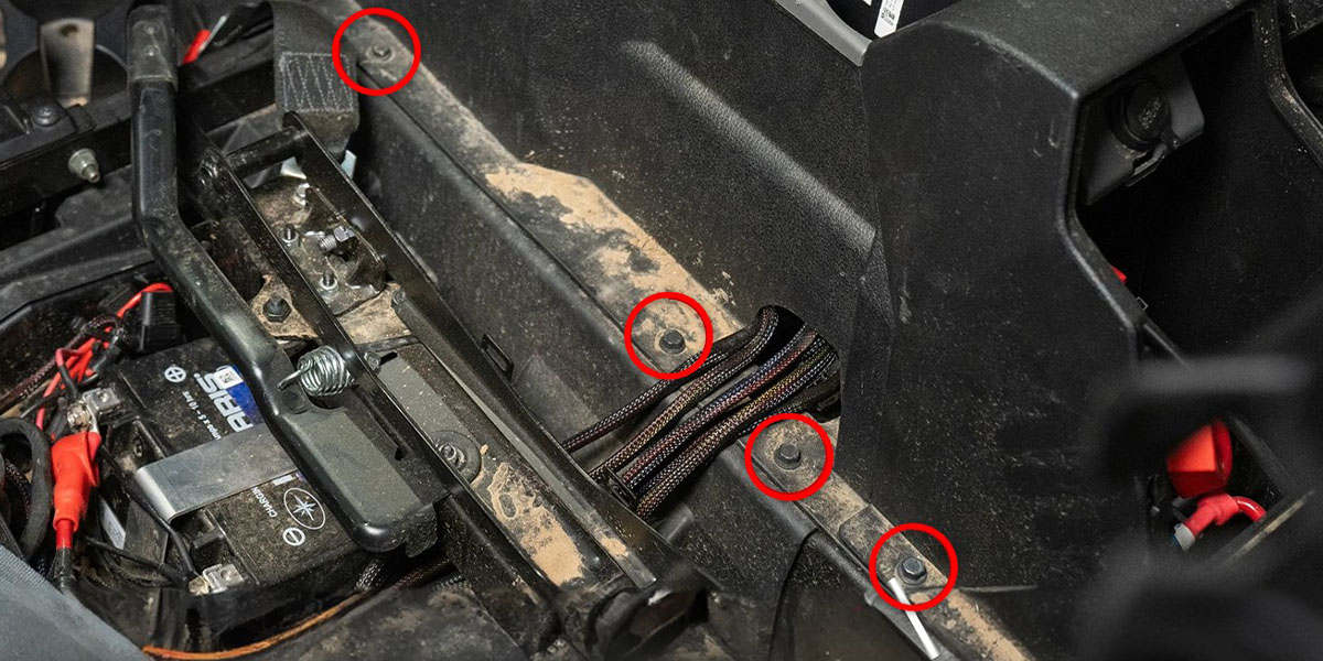
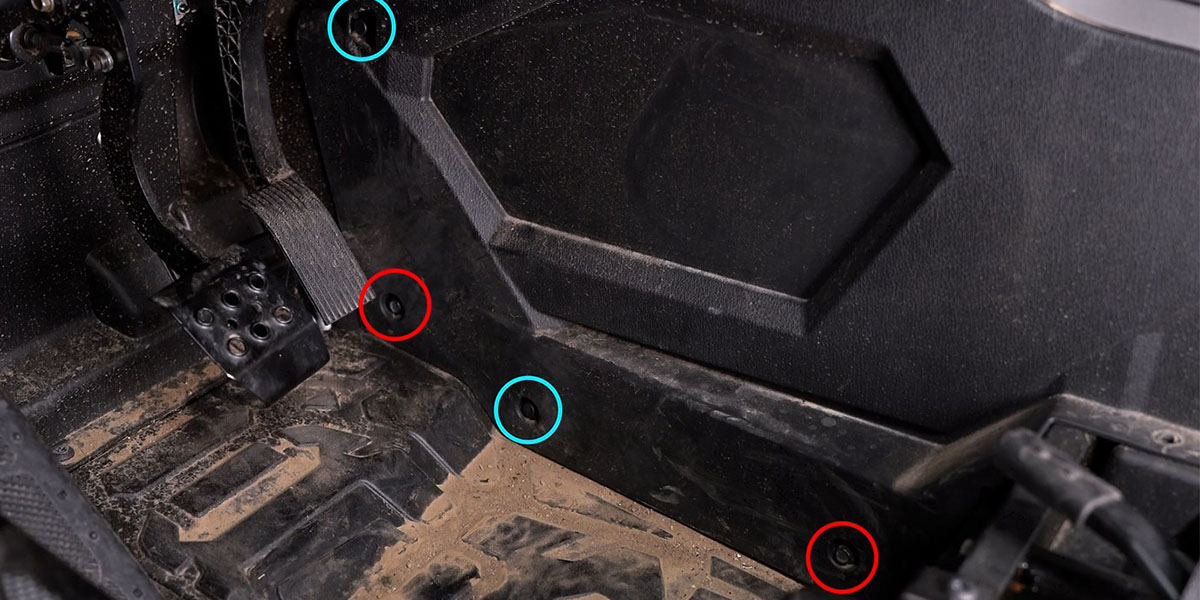
Step 7 - Remove Driver-Side Kick Panel Bolts and Clips.
With a 10mm socket, remove the two 10mm bolts (circled in red) on the bottom of the driver-side kick panel.
Then use a plastic trim removal tool to remove the two clips (circled in blue).
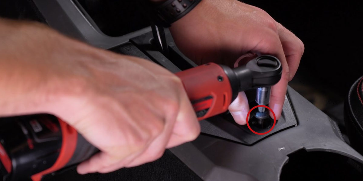
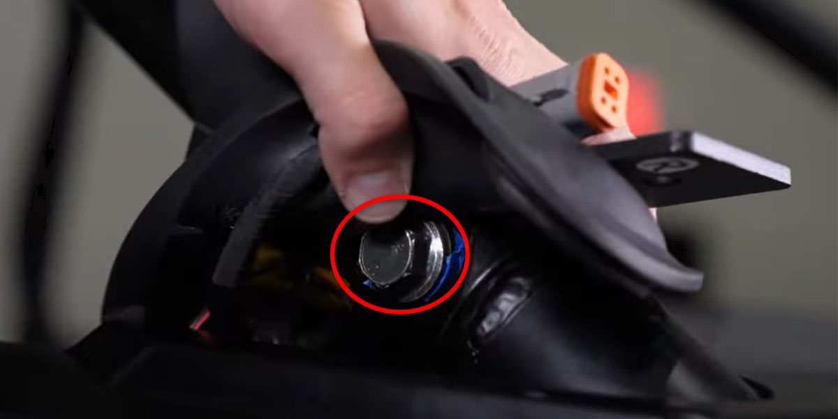
Step 8 - Remove Shifter Trim Bolt.
Lift up the rubber shift cover and use a T40 Torx bit to remove the bolt circled in red below. Then remove the shifter trim.
Step 9 - Route the White Connector Lead.
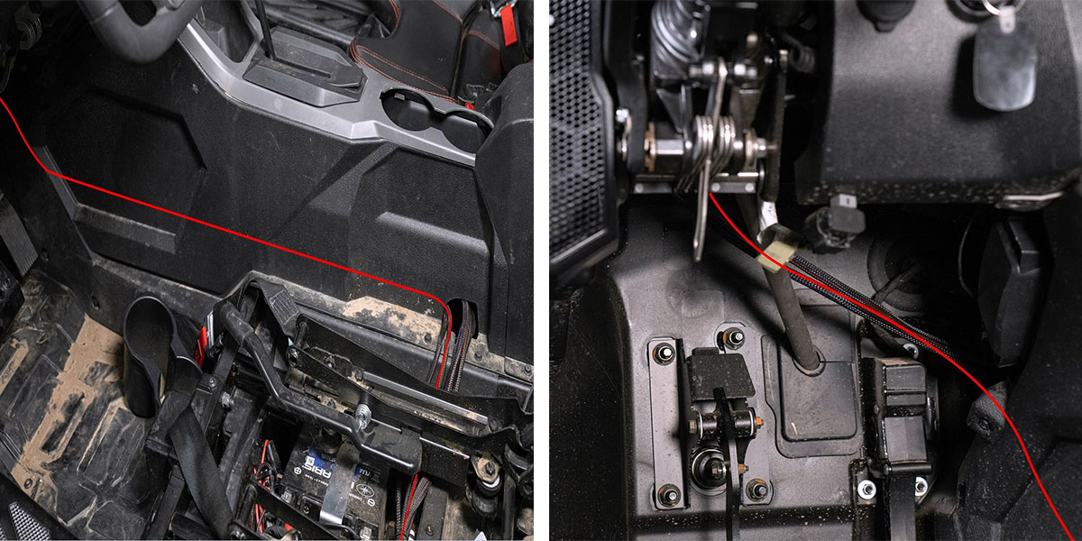
With the switch disconnected from the wiring harness, route the white connector lead from the battery under the center console into the cup holder area. Then continue routing the connector down and around the shifter and toward the fire wall.
Note: Be sure to route the connector around the shifting bracket, not through it.
Then continue routing the lead towards the firewall and out of the hole (circled in red) at the back of the passenger side kick panel.
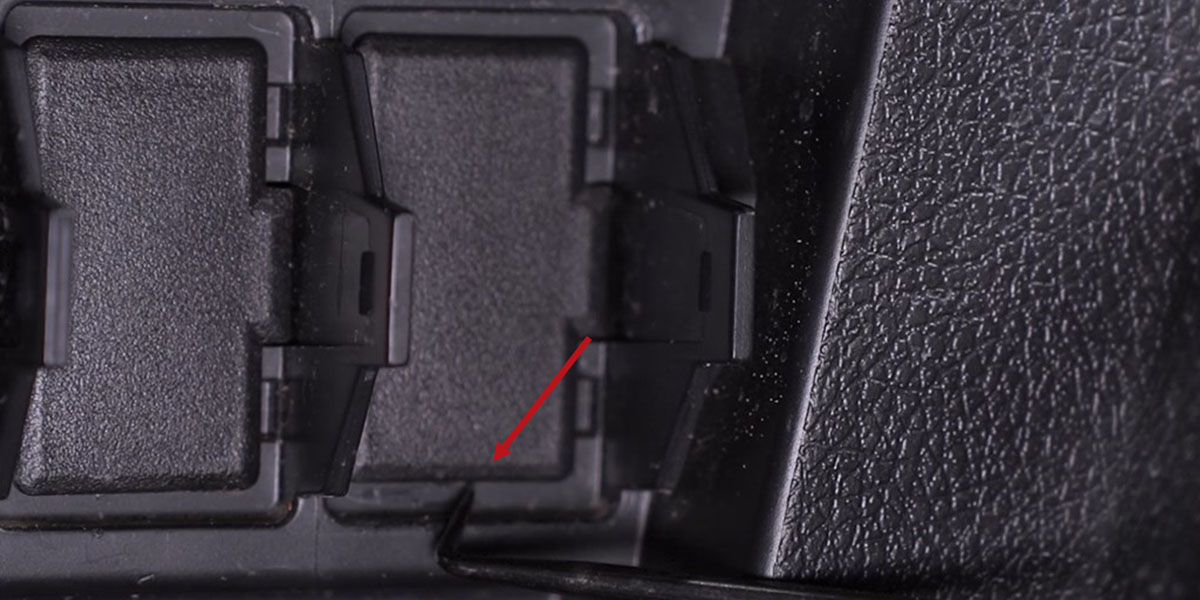
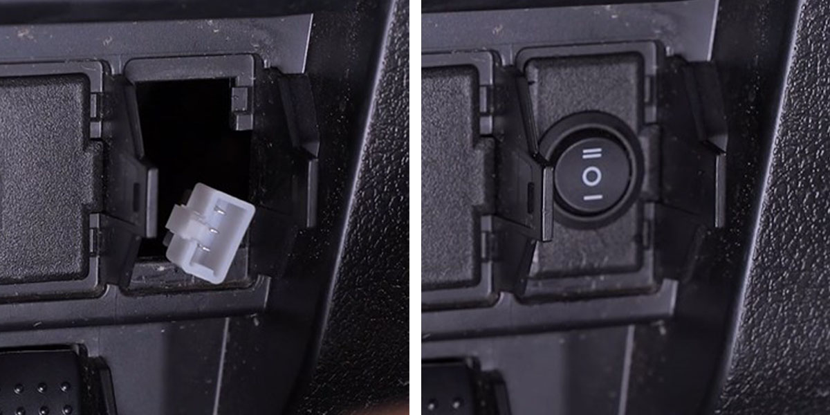
Step 10 - Remove Switch Blank.
To mount the switch, use a pick tool to pop out one of the factory switch blank covers.
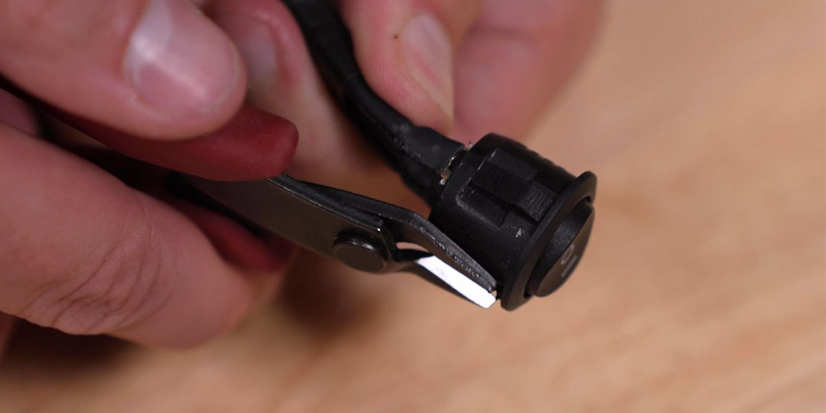
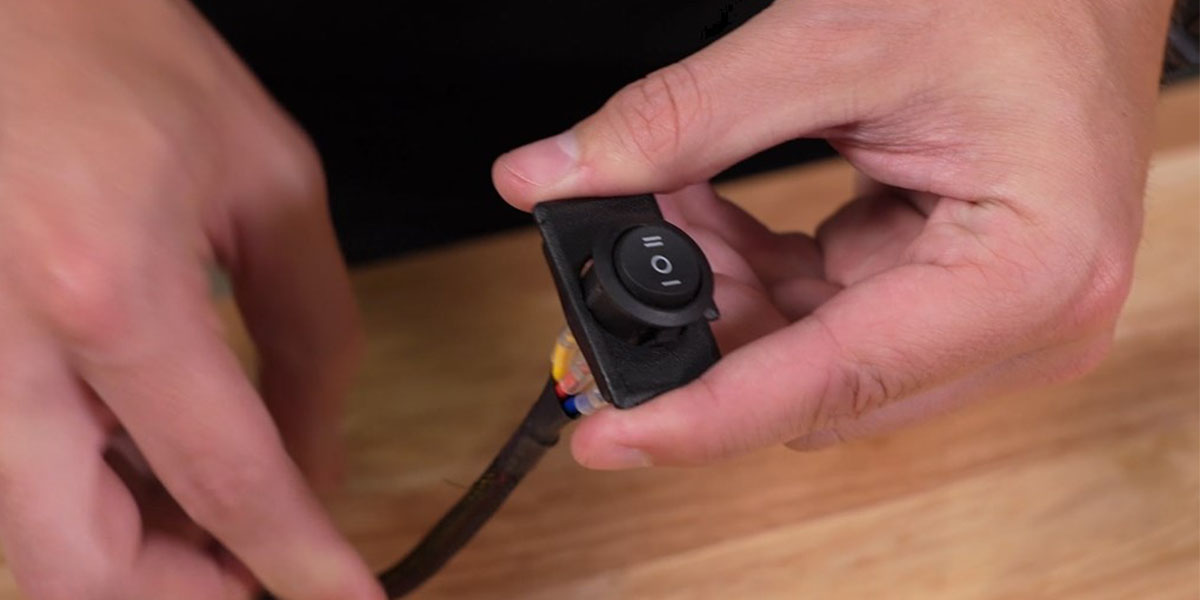
If you're going to use the included round toggle switch, use a pair of flush-cut pliers to trim the key slot off of the switch as shown below.
Then use the step bit to drill a hole in the switch blank cover to about 20.5mm, or until the toggle switch fits snuggly.
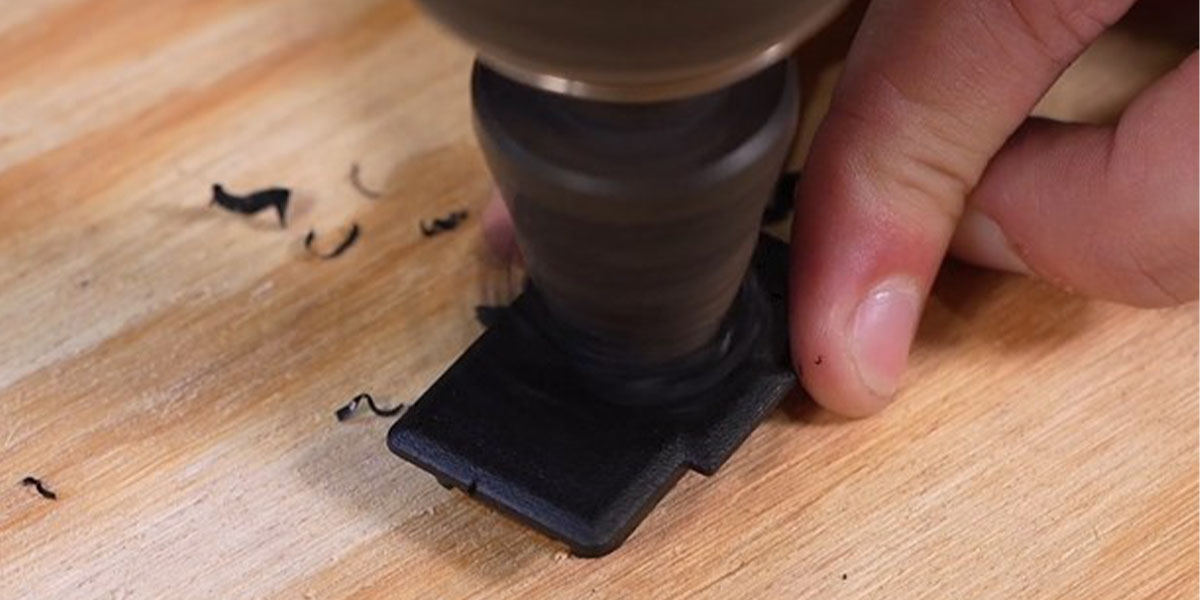
Feed the white lead of the switch through the drilled hole on the front of the switch blank. Then press the switch into place, making sure the double lines on the switch are on the top half of the switch blank cover.
Step 11 - Connect and Mount Switch.
Route the switch lead from Step 9 through the back of the switch panel where the switch blank was removed. Then connect the lead to the switch and press it into place.
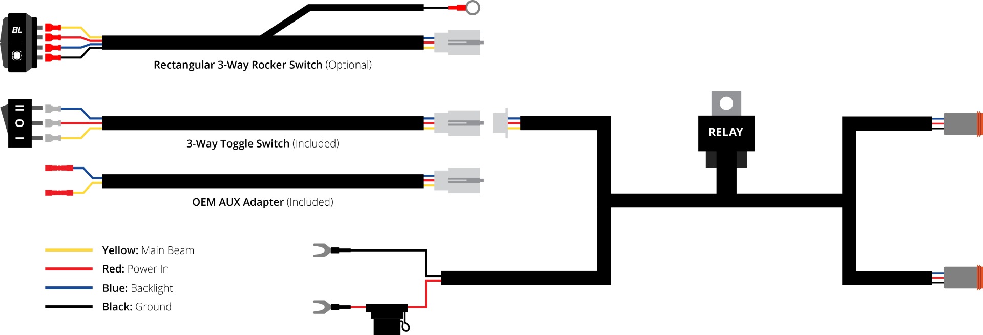
Install Rectangular Rocker Switch (Optional)
If desired, the included wiring harness can be controlled using the Diode Dynamics Rectangular Rocker Switch. To install the switch, disconnect the factory harness switch by unplugging it from the white connector on the switch lead. Connect the rectangular rocker switch directly to this connector.
Route the switch wiring to your preferred mounting location and remove the factory switch blank from the dashboard or switch panel. Insert the rocker switch into the opening until it is fully seated.
The rocker switch features integrated backlighting and must be grounded for illumination. Attach the black wire with the ring terminal to a suitable chassis ground point on the vehicle.
Step 12 - Route the DT Leads.
From the battery, route the DT lead through the bottom of the center console following the same route as the switch lead in Step 9 and coming out of the driver-side kick panel. Then cross the lead behind the steering column going up towards the A-Pillar.
Pull the DT lead out under the A-Pillar boot. Then use zip ties to secure the wiring away from any moving parts and to clear the driver's side foot well.
With the second DT lead, we will follow along the switch lead from Step 9 to the passenger-side kick panel. Then cross over behind the dash and up to the passenger-side A-pillar boot.
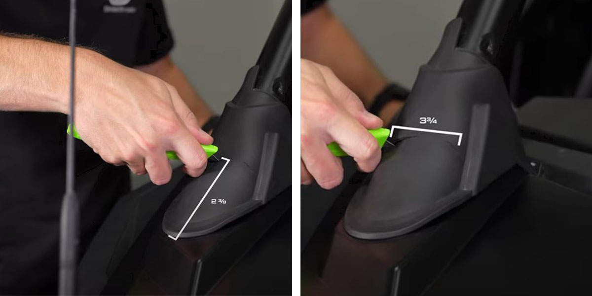
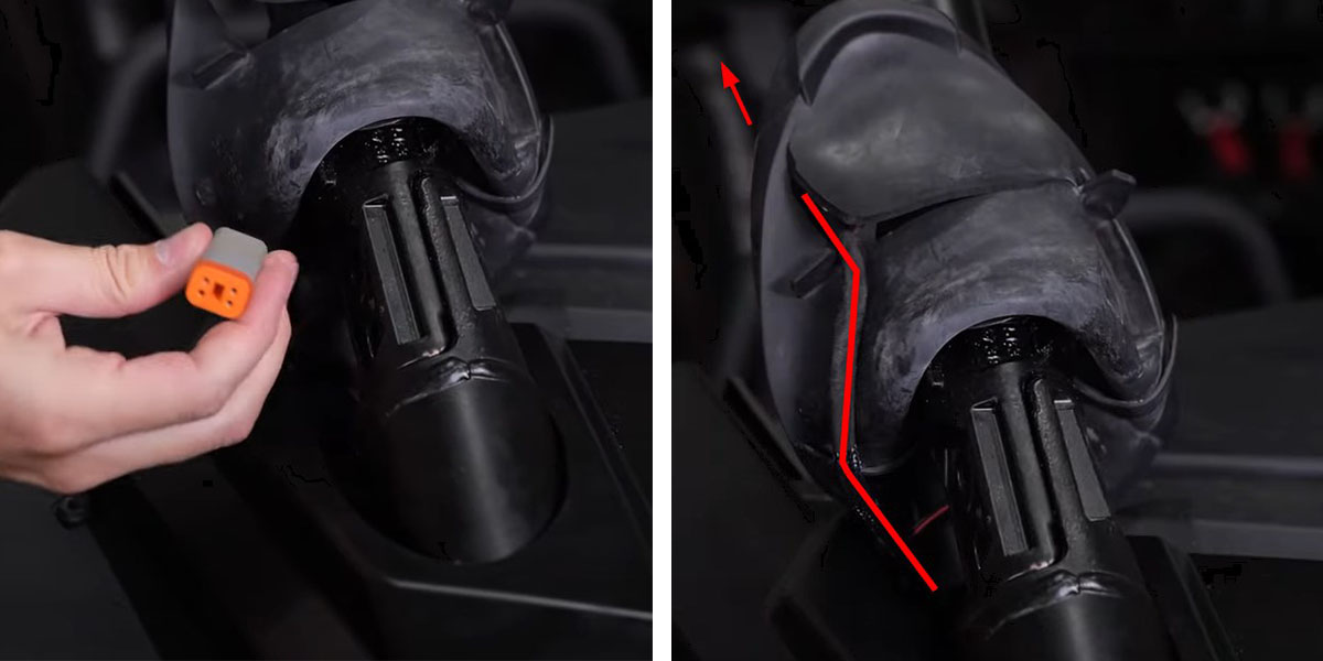
Step 13- Peel Back Rubber Boot.
With a utility knife, cut a slot in the rubber A-Pillar boot 2 and 3/8" from the bottom and about 3 and 3/4" long.
Then peel back the rubber boot to reveal the two 18mm bolts.
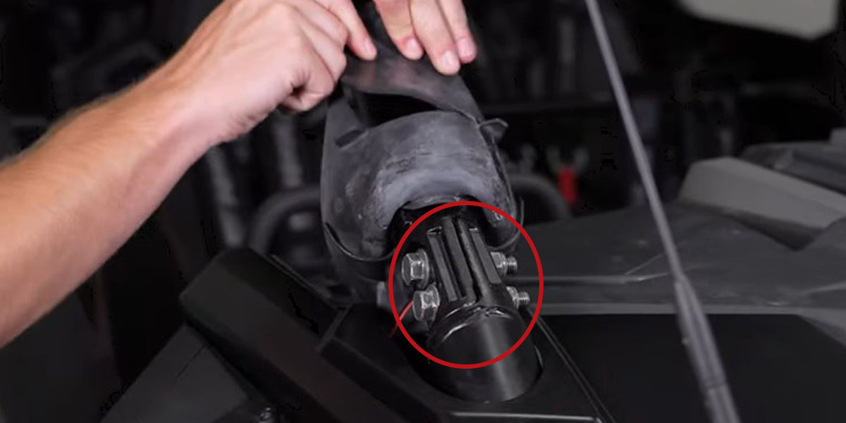
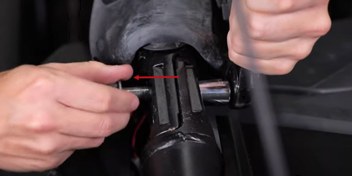
Step 14 - Remove A-Pillar Bolts.
Use an 18mm socket to remove both of the bolts.
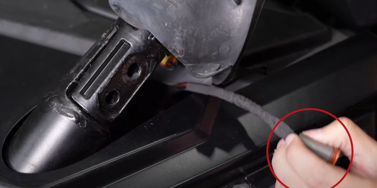
Step 15 - Route Passenger Side DT Connector.
Pull out the DT Connector that was routed in Step 12. Then put it through the slot that was cut in the rubber boot during Step 13.
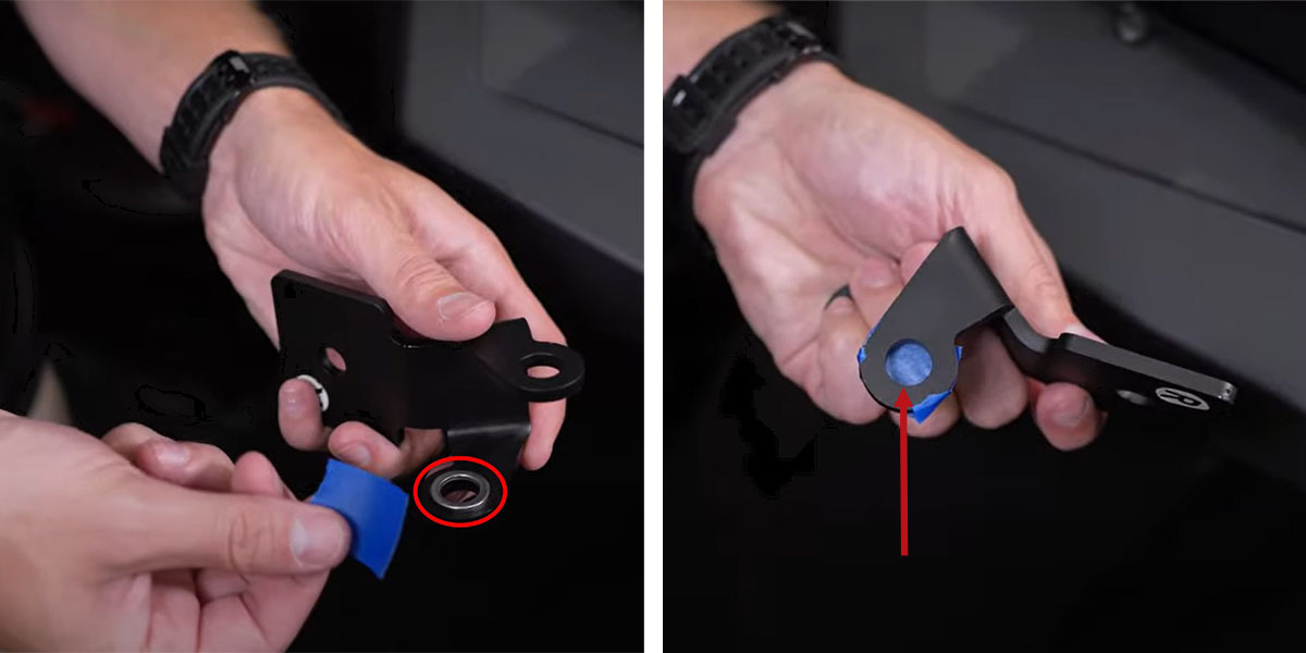
Step 16 - Tape Washers To Bracket.
Prepare to bolt the ditch light bracket to the A-pillar bar using the factory bolts removed in Step 14 and the included washers. The washers will be placed between the A-Pillar and the bracket.
An easy way to do this will be by using a piece of masking tape to hold our washers (circled in red) to the inside of the brackets and simply press the bolts through the tape once the bracket is in place.
Step 17 - Mount Bracket.
Take your bracket with the R orientation sticker facing up and slide it through the slot you made in the boot in Step 13.
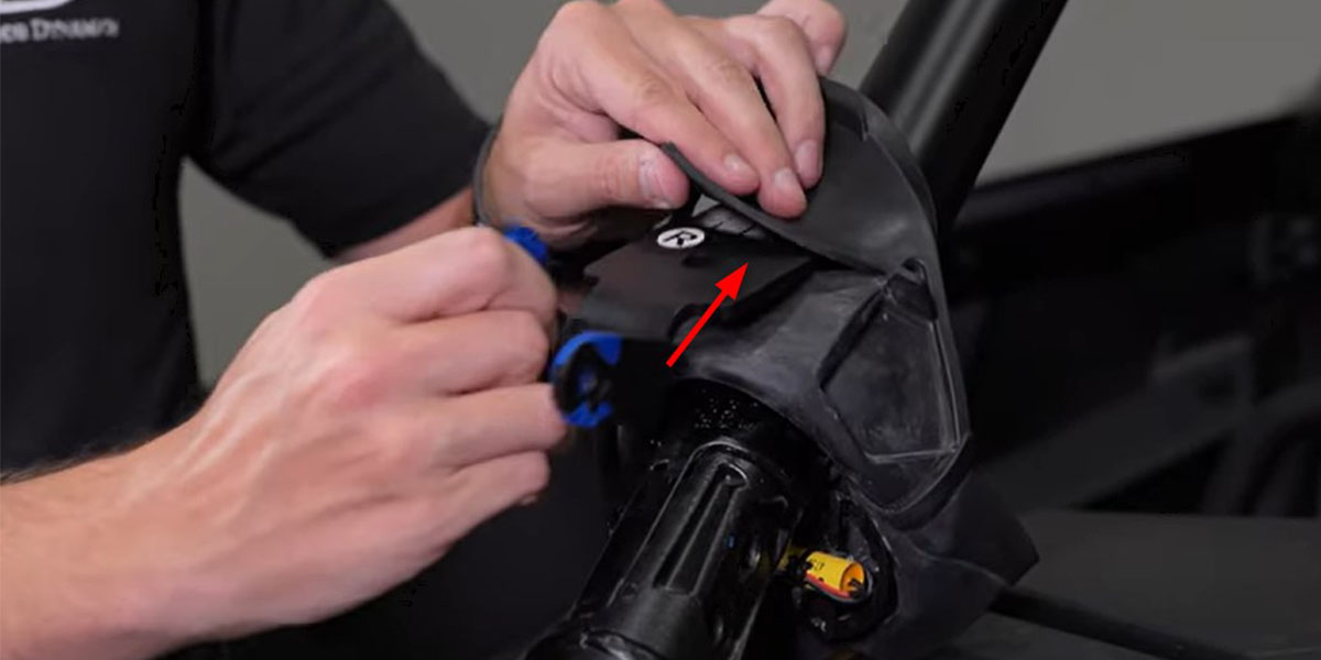
Next, pull down the bracket and boot to align the bracket holes with the A-pillar holes.
Step 18 - Secure Bracket.
Secure the bracket to the A-Pillar using the two 18mm bolts removed in Step 14.
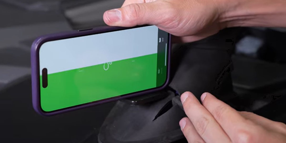
Once secured, use a level to make sure the bracket is level. Then repeat Steps 17 and 18 to mount the remaining bracket on the other A-Pillar.
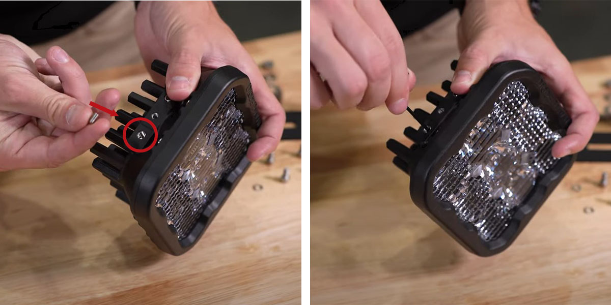
Step 19 - Assemble the SS5 LED Pod Brackets.
Assemble the SS5 universal brackets by inserting the set screws in the bottom threads using a 3/32" Allen Key.
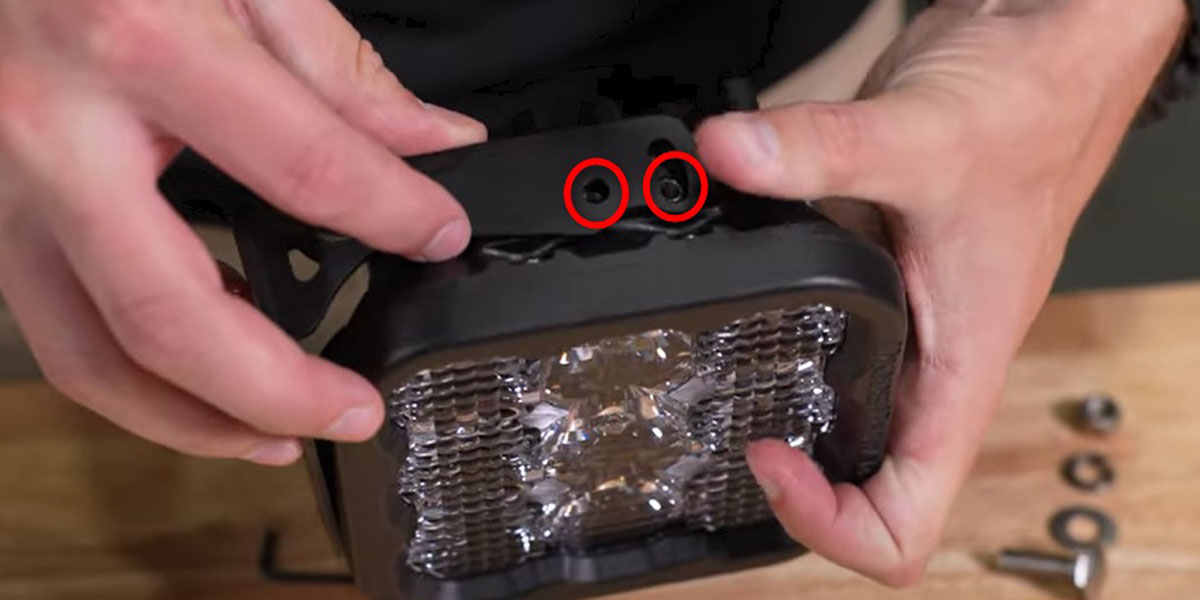
Then slide the universal bracket over the SS5s, securing them to the Pod with the included 5/32" bolts and washers.
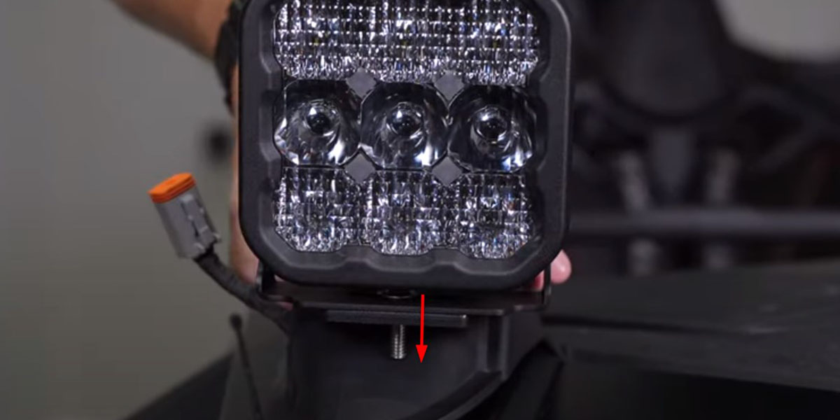
Step 20 - Mount SS5 LED Pods to Brackets.
Bolt the SS5 LED Pods to the brackets with a supplied carriage bolt, washer, lock washer, and nut. Hand-tighten them for now, leaving room for adjustment in Step 22.
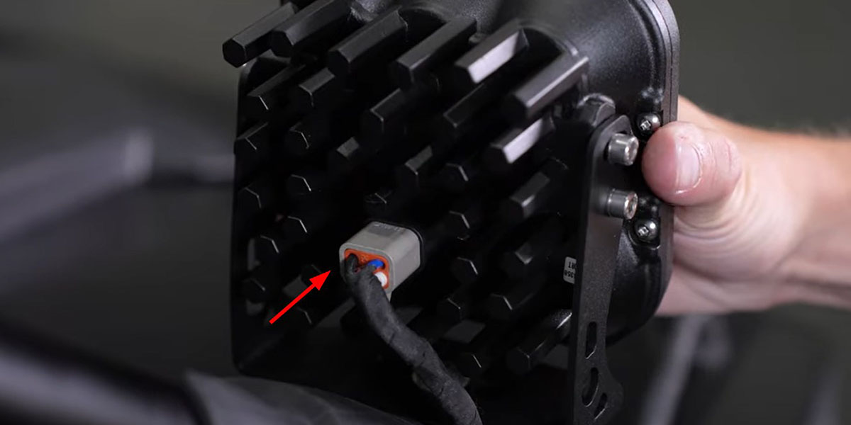
Step 21 - Plug-In SS5 LED Pods.
Plug the previously routed DT connectors into the back of the SS5 LED Pods. Then test the function of your lights.
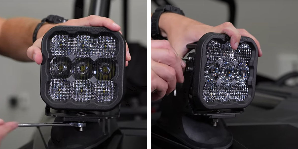
Step 22 - Make Aiming Adjustments.
To aim the LED Pod horizontally, rotate the pod left and right. Then tighten it down with a 13mm wrench.
To aim the LED Pod vertically, tilt the pods up and down. Then tighten it with a 5/32" Allen Key.
Step 23 - Reassemble the RZR.
With everything functioning and aimed properly, reassemble the RZR by reversing the steps used to take it apart. Make sure to zip-tie any loose wiring to keep it away from hot or moving parts.
Questions About the Installation?
If you have any questions or issues installing the Stage Series A-Pillar Pod Kit for the 2020-2023 Polaris RZR Pro, please contact us for further assistance.
Where Can I Buy A 2020-2023 Polaris RZR Stage Series A-Pillar Pod Kit?
If you’re ready to upgrade your 2020-2023 Polaris RZR Pro with the Stage Series A-Pillar Pod Kit, you can purchase one by clicking here or by using our dealer locator to find a dealer near you.
Want to know more about Diode Dynamics products? Visit DiodeDynamics.com and subscribe to our newsletter for new product releases and more!
This Installation Guide is for the following SKUs: DD7634P, DD7635, DD7637, DD7639, DD7641, DD7636, DD7638, DD7640, DD7642.
Share This Post